This chapter explains the operation and control of the EcoDrive hooklift using the CBW controller, that is located inside the cab.
The hooklift can also be controlled with the use of JOAB's radio controller or wired remote controller. These are not standard equipment and must be ordered as an extra option. For further information regarding the radio controller see "Radio Controllers".
CBW controller
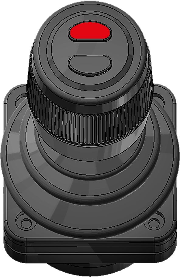
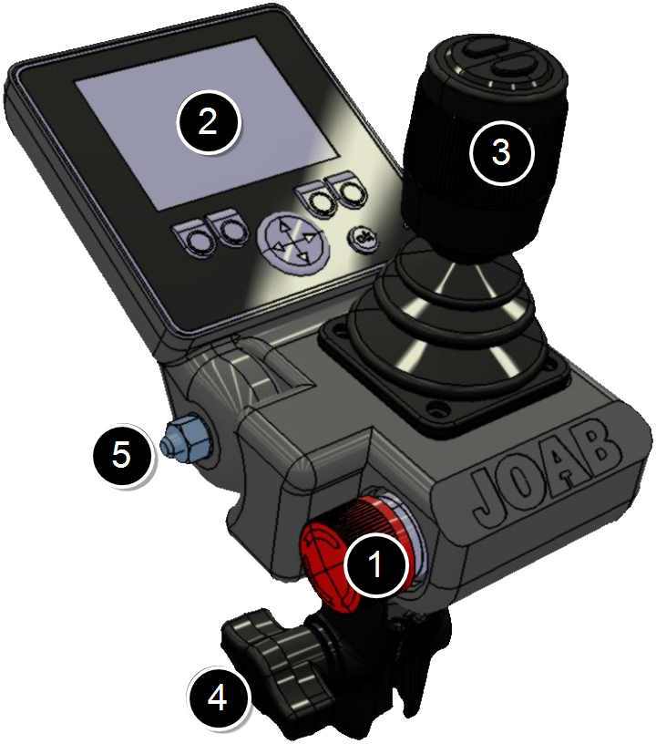 The CBW controller has both a display and control-stick, as shown, and is used to control all functions of the hooklift.
To watch a video of the controller in use, click the following link: video.
Certain functions, such as the operation of the hydraulic pump, can be installed on the cab instrument panel, either in addition or separate from the CBW controller, as required.
The CBW controller has the following main parts:
- Emergency Stop
- User Interface
- Control stick
- Mounting bracket
- Screen lock screw
The emergency stop button is used in case of an emergency. Once pressed, all functions of the hooklift that could cause injury are disabled. For further information regarding the emergency stop, refer to "Emergency Stop".
The user interface of the CBW controller has a 2.8 inch colour display. It is configurable. It is possible to display one of five different page setups. Each page setup can have six user defined functions, such as turning lights on. For further information see "Page Setups".
If the PTO is tuned off, the display will also turn off. However, if there are any active warnings the display will show the warnings (refer also to "Warnings").
The control-stick is used to control the basic functions of the hooklift, such as tipping. For detailed information regarding its function, refer to "Control Stick Function".
The mounting bracket is used to mount the unit inside the cab. Normally it is mounted onto the driver's A-post. However, it is also possible to mount it onto the driver's right arm rest (an extra cable is required to do this). This is ideal for vehicles equipped with a snow plough. Refer to "APC Transfer Kit " for further information about this.
A split setup is also possible with the control-stick mounted next to the driver's seat and the display on the A-post. This however is not ideal for snow ploughs.
User Interface
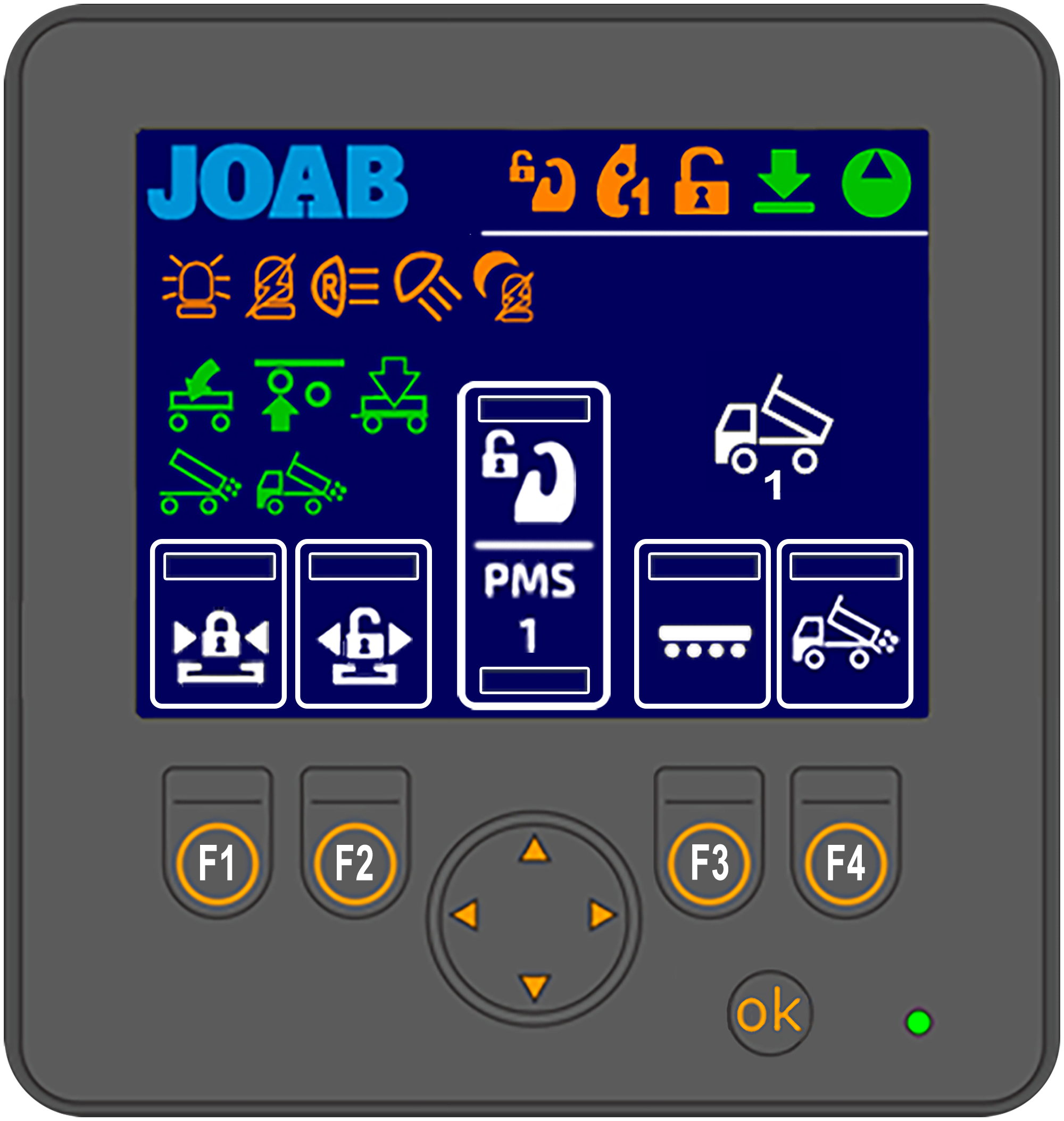 Shown opposite is an overview of the user interface.
The areas marked with a white rectangle on the screen are programmable. The user can set which functions are placed there. These functions are activated by pressing the corresponding buttons: F1–F4 and the UP/DOWN arrows. For further information on how to set these functions, refer to "Function Buttons" below.
The function icons (F1–F4 and the UP/DOWN arrow buttons) that are displayed in the user interface is dependent upon which page setup is selected. There are five different page setups. To switch between these press either the left or right arrow button located below the screen. For more information see "Page Setups".
All other icons that are displayed on the screen (not the user defined functions) simply provide feedback to the user regarding the status of the hooklift, which page setup is active, and active functions, such as lights on etc.
See "Icon Definitions", below for a list of the icons and their function.
Icon Definitions
Provided below is a list of the most common functions available in the user interface and their meaning. Note, not all functions listed below are activated for all installations. Some of the functions are optional extras, these are marked with an asterisk (*).
Functions that can be selected for the programmable areas (F1–F4 and the UP and DOWN buttons) are coloured white. All other buttons (orange and green) simply provide feedback to the user as to whether or not they are active.
For a more complete list of the functions that the CBW controller can use, refer to "CBW controller Icons"
| Icon | Function | Icon | Function |
|---|---|---|---|

|
Hydraulic Pump ON |

|
Work light*3,4 |

|
The hooklift is in its lowered status. |

|
Reverse light*3 |

|
Tipping forbidden. The: RUP, PMS, or crane dowel sensor is active. |

|
Start/stop the crane* |

|
Center lock is OPEN |

|
Draw bar* |

|
Safety hook is OPEN** |

|
AHF (Adjustable hydraulic flow) start/stop* |

|
Hydraulic lock is OPEN |

|
FFD2. Read NOTE 2 below. |

|
Night mode. See "Background Light" |

|
Salt spreader* See also "Icon Definitions APC". |

|
Automatic reverse light - ON3. Press 2 times to activate. |

|
Activate snow plough slush flap* |

|
Automatic flashing light - ON3. Press 2 times to activate. |

|
Front snow plough - float mode* |

|
Hydraulic lock - CLOSE |

|
Automatic plough UP on reverse* |

|
Hydraulic lock - OPEN |

|
Position memory system* |

|
Safety-hook - LA models* |

|
Turtle mode - used for heavy or delicate loads. |

|
Flashing light*3 |

|
Extend the underrun protection |

|
Rotating light*3 |

|
Retract the underrun protection |

|
Spreader hatch - VEHICLE* |

|
Automatic hatch - TRAILER*1 |

|
Automatic hatch - VEHICLE*1 |

|
Air dump - TRAILER* |

|
Spreader hatch - trailer* |

|
Axle lift - TRAILER* |

|
Tip trailer - UP* |

|
Tip trailer - DOWN* |
*Extra option. Not standard equipment. **LA models only.
NOTE1: The above functions: Automatic flap - VEHICLE and Automatic flap - TRAILER can be operated without the hydraulic pump being turned ON. Simply keep the icon pressed for 10 seconds to activate them without turning the pump on.
NOTE2: FFD must be de-activated when working with bodies that have dowel pins that are used to anchor the body onto the vehicle. If FFD is active, damage can occur. See "Friction Free Drive - FFD" for further information.
NOTE3: This only applies to JOAB equipment installed on the hooklift. It does not apply to equipment installed by the manufacturer of the vehicle.
NOTE4 For Scania vehicles, this can also be activated automatically when the vehicle is put into reverse. To do this, press the load light button on the drivers door for 5 seconds.
Page Setups
The user interface can display one of five main page setups, each configured with user defined functions. In addition, a page that displays information regarding the position of the hook on the hooklift can also be displayed. See "Hook Positioning" below. The pages available are listed below. The page setup that is active is displayed in the bottom right-hand side of the screen with one of the following icons (see "User Interface").
| Icon | Description | Icon | Description |
|---|---|---|---|

|
Vehicle setup_1 |
|
Lighting setup |

|
Vehicle setup_2 |

|
Snow plough setup |

|
Trailer setup |

|
Hook positioning display |
To switch between these page setups, simply press either the left or right arrow button below the display.
The number of menu page setups that are accessible via the left and right arrow buttons can be configured as required (1–5 page setups). In the example shown below, three page setup are selected, these are shown with a green rectangle below them. The three active page setups will be visible when the left/right arrow buttons are pressed.
To configure which of the page setups are available when the left and right arrow buttons are pressed, follow the procedure below:
-
 Press and hold down the OK button and press either the left or right arrow button at the same time for a few seconds.
 - Select the desired page setup from those displayed and then press the OK button to either activate it or de-activate it (active page setups have a green rectangle below them).
- Press and hold down the OK button for a few second to save the new settings.
The screen will then display the menu page options as shown.
Hook Positioning
 The hook position page option displays the position of the hook. This is an optional extra. For it to work, an additional sensor must be installed on the hooklift.
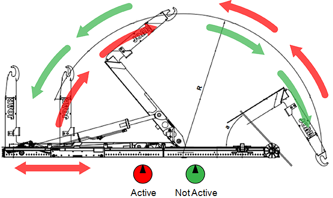
As shown opposite, the position of the hook and its angle are displayed in the user interface whenever this menu page is selected (see also "Page Setups").
This function is dependent on the hooklift's sensors. If the sensors malfunction or they are incorrectly positioned, the information displayed in the user interface will be incorrect. The actual information provided should be seen as an approximation and not an exact value.
Function Buttons
Each of the five page setups in the user interface can be configured with six personal functions. The icons for the selected functions are placed at the bottom of the user interface (shown in white rectangles, see "User Interface"). These functions are activated by pressing the corresponding function buttons below the screen: F1–F4 and the UP/DOWN arrow buttons.
To set the desired function associated with the function buttons, follow the procedure below:
- Press and hold the OK button while simultaneously pressing the function button that is to be changed.
- The current icon set for that function will be displayed with a green rectangle around it, as shown below.

- Use the UP/DOWN arrow buttons to select the desired function.
- Press the OK button.
It is not possible to select all icons in each page-setup. For example, all icons related to the operation of a snow plough are only available for selection when in the snow plough page-setup.
Background Light
The background light for the user interface can be adjusted as required. This function allows the user to quickly adjust the background light so that it is possible to read the display, when for example, there is a lot of sun shining on the display. Or dim the lighting at night.
To adjust the background light simply press the OK button with a short press, repeatedly, to switch between 100%, 20%, and 0% background light. If the lighting is set to 20%, the night mode iconwill be displayed in the CBW controller.
The display will automatically turn off whenever the hydraulic pump is off. It will only remain on if there is a warning to display, as listed under "Warnings" below.
Warnings
The user interface will display warnings whenever the hydraulic pump is not in operation. These warnings display an icon or text indicating the following states:
| Icon | Meaning | Icon | Meaning |
|---|---|---|---|

|
The hooklift is not fully retracted. It is not in its parked position. |

|
The hydraulic-lock is open. |

|
The center-lock is open. |

|
Safety-hook is open (LA models). |
| Text | Meaning |
|---|---|
|
No CAN Communication |
The CBW controller has no communication with the CAN bus network. |
|
High Oil Temperature |
The temperature of the oil for the hooklift is high*. |
|
Low Oil Level! |
The oil level for the hooklift is low. Turn the pump off immediately. Top the oil level up before operating the hooklift. Failure to do so can cause damage*. |
*A sensor must be installed in the hydraulic oil tank for this function to work. This is optional equipment.
Control Stick Function
Listed below in Table 6 are the functions that the control-stick has. To watch a video of the controller in use, click the following link: video.
For information regarding the control of snow ploughs refer to "Active Plough Control - APC".
To view a video showing how to control the hooklift click this link: Video
| Tip Up | Fast Tip Up FTS1 |
Automatic Tip Lower ETM |

|

|
|
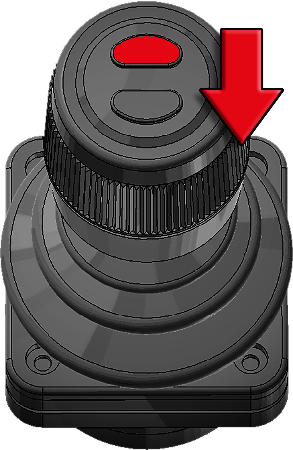
| Pull backwards | Bottom button pressed
and pull backwards |
Top button pressed and hold forward for two seconds until the parked icon flashes |
| Tip Down | Fast Tip Down FLS(+)1 |
Fast unload FDS1 |

|
|

|
| Push forwards | Bottom button pressed
and push forwards |
Press the bottom button and pull backwards. |
| Trailer Tip UP3 |
Trailer Tip DOWN3 |
Fast load FDS+1 |
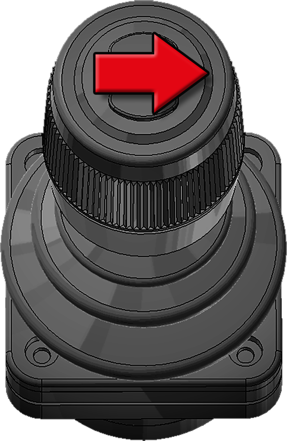
|
|
|
| Push the knob to the right | Push the knob to the left | Press the bottom button and push forward. |
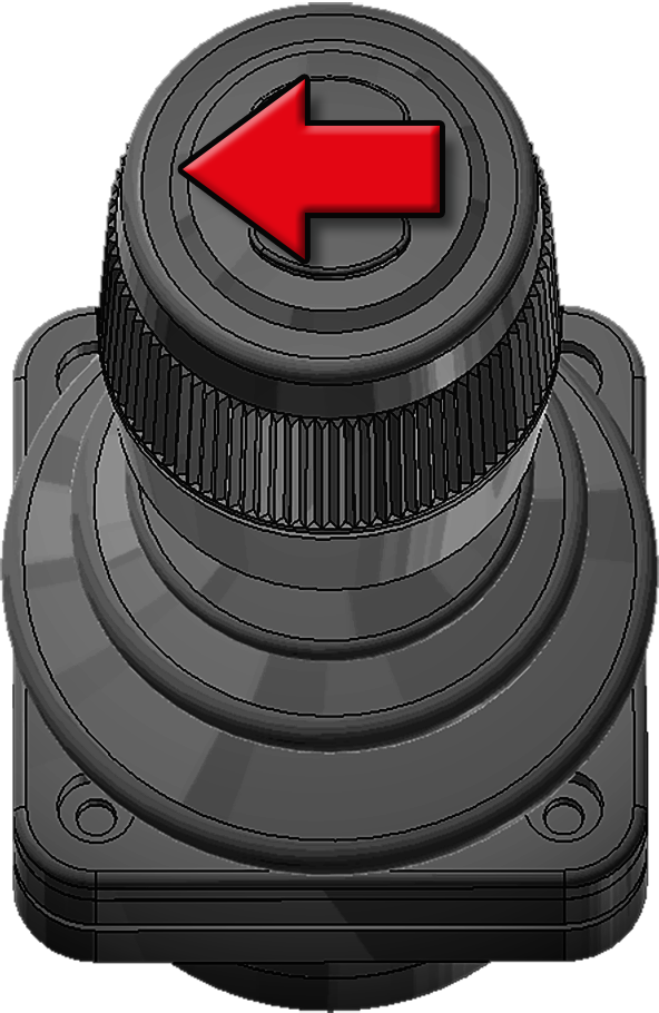
| Folding-Hook-Post
UP2 |
Folding-Hook-Post
DOWN2 |
Auto Cycle Unload ACS1 |
|
|
|
|
| Push the knob to the right | Push the knob to the left | Top button pressed
and pull backwards |
| Extending-Section
OUT |
Extending-Section
IN |
Auto Cycle
Load ACS1 |
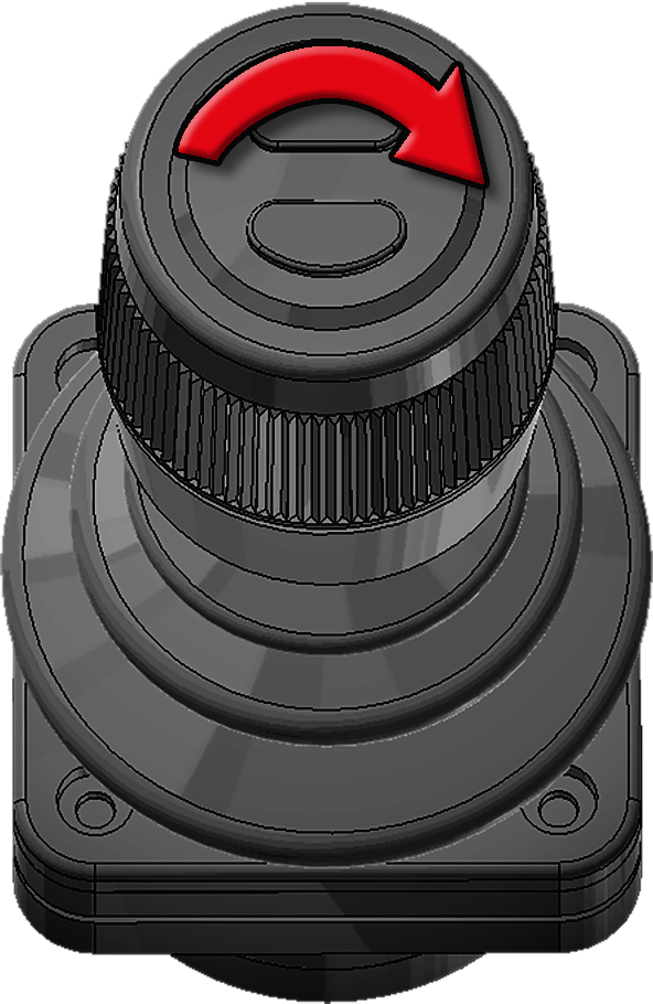
|
|
|
| Turn the knob clockwise | Turn the knob anti-clockwise | Top button pressed
and push forwards |
1 Extra option, for further information see "EcoDrive Optional Functions". 2 LA models only. 3 L models only.
Diagnostics and Statistics
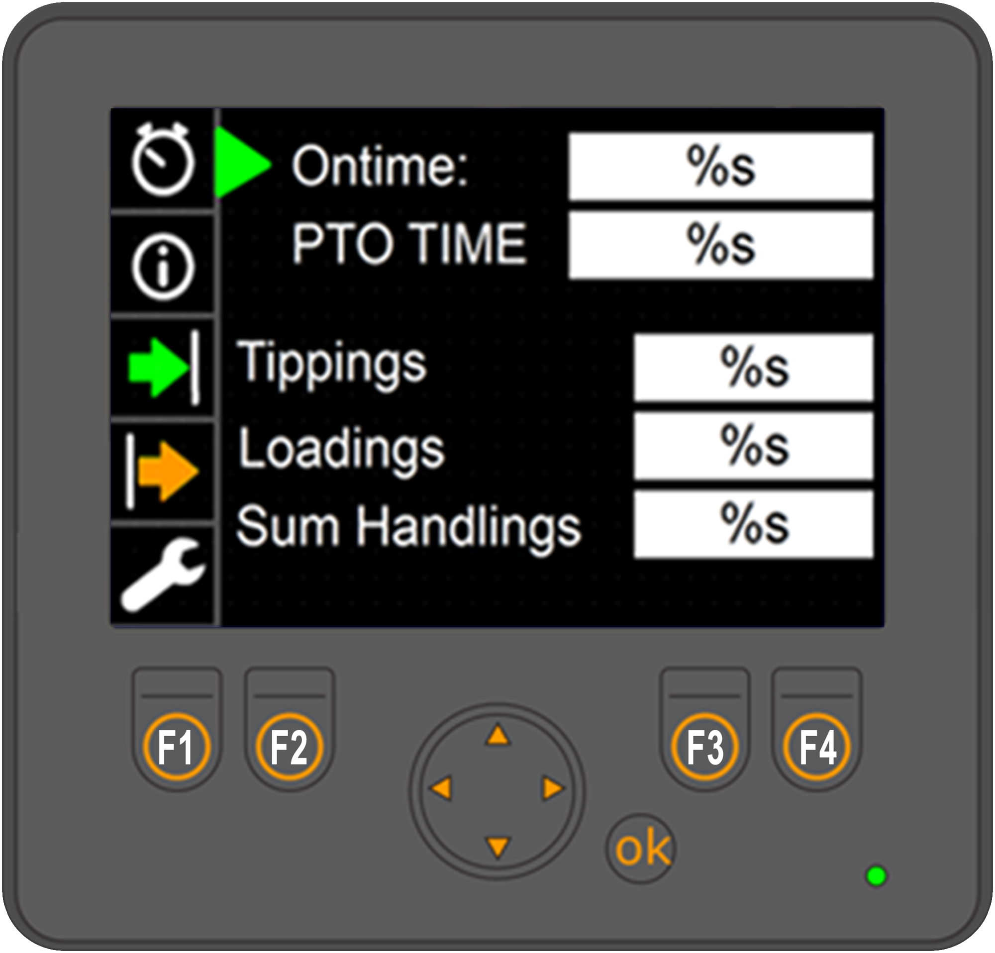 The CBW controller has a diagnostic and statistics page that the user can use to view information about the hooklift.
To access the menu, first make sure that one of the main menu pages is displayed and then press and hold down the OK button for three seconds. The screen shown opposite will then be displayed.
There are five main sections located on the left of the screen to select from.
Use the arrow buttons to navigate the menu. The up and down arrow buttons navigate through the menu. The left and right arrow buttons allow the user to select from options when applicable.
To exit the diagnostic and statistical menu, press and hold down the OK button for a few seconds.
Menu Descriptions
Provided below is an overview of the menu options available in the Diagnostics and Statistics page. To view a full view of these menus refer to "Diagnostics Page". Or alternatively click on the icons below.

The first menu option, shown above, provides statistical information regarding the use of the hooklift.

The second menu provides information regarding the version of software installed, the hooklift model, and serial number of the hooklift. It is also possible to open both the Service Menu and CAN Menu from this page.

The third menu option provides diagnostic information regarding sensors and input signal status for the hooklift.

The fourth menu option provides information regarding outputs from the master module.

The fifth menu option provides an emergency operation mode and the option to calibrate the hooklift. For further information about the emergency operation refer to "Emergency Operation".
Emergency Stop
In case of an emergency, such as a hydraulic leak or risk of injury, an emergency stop button is fitted to the CBW controller (see "CBW controller"). Pressing the emergency stop button will stop all functions of the hooklift immediately. To reset the emergency stop function, turn the pump off, reset the emergency stop button, and then restart the pump.
Emergency Operation
Caution must be taken when using the emergency operating system. The hooklift's safety system is disengaged. There is a risk of damage to the hooklift or injury if due care is not taken. Before using the emergency override make sure that you are fully aware of its operation.
It is possible to operate the hooklift even though the hydraulic lock is closed. Operating the hooklift when the hydraulic lock is closed can cause damage to the body. Make sure to unlock the hydraulic lock first, before performing: load, unload, and shunting operations. The lock must be closed for tipping operations.
In the event of a failure in the hooklift’s system, it is possible to still operate the hooklift using the emergency system. To activate the emergency system, follow the procedure listed below:
If in any doubt about the use of the emergency override, contact JOAB for advice before using it.
-
 Turn the hydraulic pump on.
 - Press and hold down the OK button for five seconds, to open the "Diagnostics and Statistics" page, as shown.
- Press the down-arrow button so that the spanner icon is selected on the left menu.
- Press and hold down buttons F3 and F4, as shown, at the same time, for five seconds, so that the text "Fail Safe (Felsäkert läge)" is displayed in the user interface.
- Press and hold down the OK button for five seconds to return to the main menu.
- To operate a hooklift function, press and hold down the function's icon for ten seconds.
once the text "Fail Safe" is displayed in the user interface, the emergency operation will be active for five minutes only.
Pressing either the Swedish flag (F1) or the American flag (F2) will change the language of the displayed text, accordingly.
EcoDrive Standard Functions
EcoDrive hooklifts come equipped with a number of standard functions, as listed and described below. In addition, it is also possible to order optional functions. For information regarding optional functions, see "EcoDrive Optional Functions".
The following functions are included as standard with EcoDrive hooklifts. For further information, click on the respective function.
Intelligent Pump Control - IPC
The EcoDrive system determines when the pump needs to be activated. When the pump is turned on, it will only operate when power is required, as determined by the system.
EcoDrive Pressure Control - EPC
The system is always operated using optimal hydraulic pressure. This is based on the function that is being operated. The system is self-calibrating and can work from 50 bar to 350 bar. Optimized pressure control allows for reduced response time.
Fast Lowering System - FLS
Fast lowering with intelligent speed compensation allows the driver to lower a body at maximum speed, when tipping, either with a full or empty load. This occurs automatically and is controlled by the EcoDrive system.
Smartlock System - SLS
The hydraulic lock is operated stepless. The system's sensors detect when the lock is open. When the lock closes, the system ensures that the body is centered, automatically.
EcoDrive Load Holding - ELH
 EcoDrive's load-holding-valve allows for control of the hooklift in a completely new way. The new system uses all available kinetic energy to control a load. This in turn saves up to 70% in energy savings. The energy required to perform a movement is identified with the help of the existing load. If the system determines that the operation can be performed without the use of the pump, the operation will be performed completely stepless.
The load-holding-valve also has integrated safety features. An example of these features is the fast-closing hydraulic valves that are used for emergency stops. There are also less components in EcoDrive's valve system, which in turn increases reliability.
Electronic Cylinder Damping - ECD
Integrated electronic end position adjustment for all cylinders. This guarantees smooth and responsive control at end positions, when operating the hooklift.
Electronic Speed Control - ESC
Speed adjusted movement sequences of the hooklift in the outer operation areas.
EcoDrive Tipper Mode - ETM
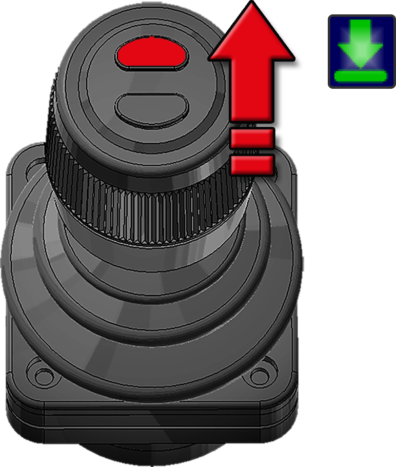
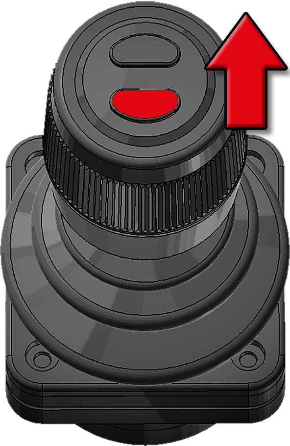
ETM allows the operator to lower the body automatically, when in tipping mode. When activated, the body will lower itself using its own weight, the operator does not need to operate the control-stick. The body is lowered at a controlled and safe speed.
The operator must be fully aware of the environment and area around the vehicle before operating this function. Failure to do so can lead to serious injury or damage. To deactivate this function, either press the top button on the control-stick (the button without a small raised dot on it) or use the control-stick and tip up.
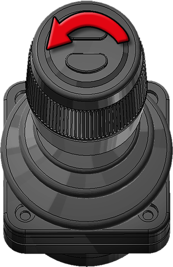
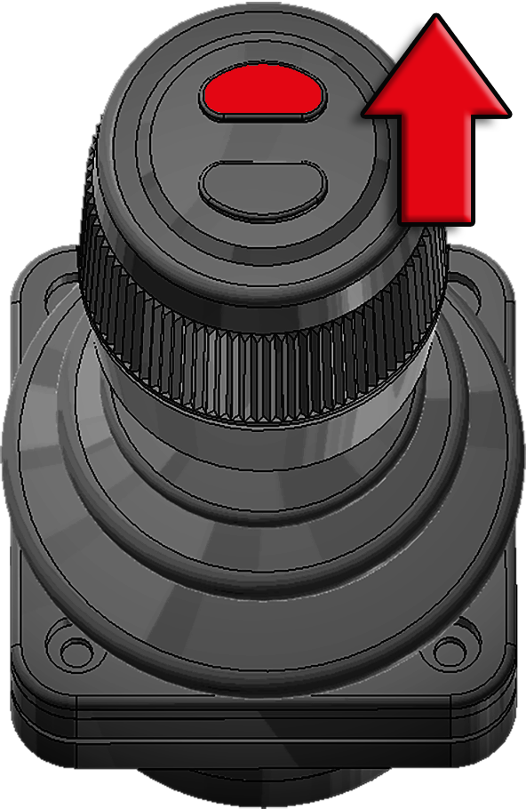
To activate this function, simply press and hold the top button (the button without a small raised dot on it) on the control‑stick while pushing the control-stick fully forward for two seconds, until the iconfor the lowered status begins to blink – ETM is then activated and the body will lower itself. See also "Control Stick Function".
Friction Free Drive - FFD
Automatic frictionless operation of the body. Built-in rollers in the auxiliary-lifting-arms (see "Hooklift Components") assist the loading of a body and allow it to roll smoothly forwards. This reduces the stress placed on the hooklift. To activate FFD, simply press the FFD icon.
The FFD function must be de-activated when loading a body that has dowel pins. These are used to anchor the body onto the vehicle, such as a crane lift body. If FFD is active, damage will occur when loading a body with dowel pins. Make sure that FFD is de-activated. It is possible to have FFD set so that it is deactivated at every system start. Contact JOAB service for more information about this.
Tipper Safety System - TSS
The auxiliary-lifting-arms are controlled using weight based damping. Integrated flow distribution components ensure that the body is tipped and lowered safely. The auxiliary-lifting-arms retrieve and move the body to its loaded position in a smooth and precise manner.
Trailer Safety Tipper - TST
TST monitors the speed of the vehicle. If it detects that the vehicle is moving faster than 50 km/h with a raised tipper on the trailer, the tipper will automatically be lowered. The system also ensures that there is no pressure in the trailer tipper's outlet on the vehicle.The valve's position is also monitored for increased safety.
With TST, a trailer can be lowered even if the hydraulic pump is switched off. There is no need to turn the pump on.
For this function to work the trailer must have a connected body builder CANBUS so that the speed of the trailer can be obtained.
Trailer Fast Lowering System - TFS
The trailer tipper function is up to 50% faster when in lowering mode. Optimized hydraulics allow the oil to flow faster. This in turn allows the tipper to lower faster. There is no return flow that would otherwise restrict the lowering function.
Decentralized Hydraulic System - DHS
EcoDrive's hydraulic system is modular. This has enabled a 30 % reduction in the number of hoses required, which in turn reduces the risk of damage to hoses. It also provides faster response times for certain functions. The modular approach makes it very easy to expand the system. New modules, such as a plough, or other external functions, can quickly and easily be added at a later stage.
Turtle Mode
Turtle mode reduces the speed of operation for tipping and shunting operations. It is intended for use with heavy loads or situations where a more gentle movement is required. To activate turtle mode simply press the following icon.
Turtle mode performs the following actions when activated:
- Reduces the lowering brake speed when tipping and shunting.
- Activates a pre-lowering brake speed reduction in tipping mode.
- Reduces the tip cylinder speed at the rear most sweep when shunting.
The hooklift's system stores whether or not turtle function is active. If the function is active when the vehicle is turned off, it will also be active at next start up of the vehicle. To disable it, the function must be turned off.
To make the turtle mode available in the display, follow the procedure described under "Function Buttons".
EcoDrive Optional Functions
Listed below are the optional functions that can be ordered in addition to the standard functions, that are listed above. For further information, click on the respective option.
Position Memory System - PMS
Do not use PMS if Emergency Operation for the hooklift is active. See also "Emergency Operation".
The PMS sensor is sensitive to both acceleration and retardation forces. The sensor's readings can be affected by these forces. For optimum reliability make sure the vehicle is stationary when operating PMS, or at least has a stable speed.
PMS saves both shunting and tipping stop positions into memory. Whenever PMS is active, the hooklift will automatically stop at the saved stop position for shunting or tipping. If PMS is active when the system is shut down, it will also be active when the system is restarted.
- Operate the hooklift in shunting mode so that it is at the desired position and stop.
- Press the PMS 1button to turn PMS on. Short press only.
- Press and hold down the PMS 1button for at least three seconds. When releasing the button, verify that the green status bar above the PMS 1 icon flashes a few times and then remains illuminated green. This indicates that the new stop position has been successfully saved and is active.
Set the Shunting Position
- Operate the hooklift in tipping mode so that it is at the desired position and stop.
- Press the icon PMS 1button to turn PMS on. Short press only.
- Press and hold down the PMS 1button for at least three seconds. When releasing the button, verify that the green status bar above the PMS 1 icon flashes a few times and then remains illuminated green. This indicates that the new stop position has been successfully saved and is active.
Set the Tipping Position
If PMS is active a new stop position can be stored by simply keeping the PMS button pressed for at least three seconds. A short press of the PMS button activates/deactivates PMS. A long press (more than three seconds), when PMS is active, sets a new stop position for PMS.
If PMS is active and the green status bar above the PMS icon simply turns off when attempting to set a new stop position it means PMS has been deactivated instead. The PMS button was not pressed down long enough to initiate a new save.
If PMS is active and it is not possible to position the hooklift to a new stop position, turn PMS off and follow the procedures above.
Graphical display
The position of the hooklift's hook can be viewed in the CBW controller's Hook Positioning page. Refer to "Hook Positioning".
If an error exists with the PMS sensor a warning message is displayed in this page. Either "Angle sensor error", or "Angle sensor not available".
PMS Calibration
EcoDrive's system will automatically perform a calibration of the PMS sensor, if required. The calibration will occur during either shunting or tipping operations. When calibrating, PMS is deactivated and the green bar above the PMS icon will blink continuously. Once the calibration has completed the green bar will stop blinking.
Fast Lowering System Plus - FLS+
This provides a 50% decrease in the time taken to lower the hooklift in tipping mode only. This is an addition to the standard FLS. See also "Fast Lowering System - FLS".
To activate this function, simply press and hold down the bottom button (the button with a small raised dot on it) on the control-stick when lowering the body. See also "Control Stick Function".
Fast Tipper System - FTS
Intelligent, stepless, fast tipping. The system automatically senses the load on the hooklift and identifies the optimal speed for the tipping operation of the load.
To activate this function, simply press and hold down the bottom button (the button with a small raised dot on it) on the control-stick when tipping the body. See also "Control Stick Function".
Fast Drive System - FDS
Intelligent, stepless, fast drive, ensures that the body is moved backwards (unloading) at optimal speed, when shunting. The system senses the weight of the body's load and adjusts the speed accordingly, to guarantee smooth and fast operation.
To activate this function, simply press and hold down the bottom button (the button with a small raised dot on it) on the control-stick when unloading a body in shunting mode. See also "Control Stick Function".
Fast Drive System Plus - FDS+
Fast drive loading with intelligent load sensing. This is in addition to the standard function. See "Fast Drive System - FDS".
The system senses whether it is beneficial and safe to activate fast drive load. It checks if the cylinders have sufficient power gained from the load. If so, the pump is shut off and a controlled free-lowering is initiated. In addition, Fast Lowering System Plus - FLS+ is also included.
FDS+ allows for a faster shunting operation – 60% faster. This is only applicable to loads that are less than three ton.
To activate this function, simply press and hold down the bottom button (the button with a small raised dot on it) on the control-stick, while shunting. The system will then determine if it is possible to perform fast shunting. If it is possible, shunting will begin, as long as the bottom button is held down.
Service Online System - SOS
JOAB's Cloud solution for EcoDrive provides remote roadside assistance, regardless of your location.
Container Memory System - CMS
CMS ensures that the extending-section stops at a preset point when loading a container onto the hooklift. The distance that the extending-section can extend is limited. This is used for applications where a short length container is loaded onto the hooklift. It prevents the wheels of the container from contacting the hooklift.
It is possible to save two CMS stop positions. To set a CMS stop position, simply extend the extending-section so that it is located at the desired position and stop. Tap the desired CMS icon to activate it, then press and hold down the CMS icon (1 or 2) for five seconds to set the stop position.
Before using the CMS in normal operation, operate it and verify that it stops at the desired position. Make sure it does not exceed expected clearances. If necessary, reset the stop position until the desired stop position is obtained.
To deactivate the CMS position, simply press the respective CMS icon to turn it off. Alternatively, it can be temporarily overridden. To do this, press and hold down the hydraulic-lock open iconwhile operating the extending-section. This can also be done with the use of JOAB's radio controller. To do so, simply press and hold down the hydraulic lock open button on the radio controller while operating the extending-section. Refer to "Radio Controllers".
The two CMS stop positions are set during manufacture to default values. The set positions can vary depending on the length of the hooklift. Any changes made to the set positions will be saved, even if the system is shut down and restarted.
If CMS is active when the system is shut down, it will also be active when the system is restarted.
Active Plough Control - APC
There is a serious risk of injury or death when operating or working on a vehicle with a snow plough. This is particularity important to bare in mind when the Automatic plough up function is activated. The ploughs are automatically retracted when the vehicle is put into reverse gear. Make sure there are no persons near the ploughs when operating the vehicle or ploughs.
The CBW controller can be equipped with functions for controlling snow ploughs - APC. These functions allow the driver to control both a front and side snow plough. APC is able to work with both fixed and variable pumps.
It is also possible to install an external plough that is operated by its own control unit. For information about this refer to "External Plough Systems".
As an extra option, APC can also be controlled using JOAB's remote radio controller or JOAB's wired remote controller. Both these allow the operator to control the loading and unloading of ploughs while having a good visual overview of the process. For further information regarding the radio controller, refer to "Radio Controllers". For further information regarding the wired remote controller, refer to JOAB Online Manuals - Accessories.
The CBW controller can be installed on the driver's arm rest, which is ideal for APC. Refer to "APC Transfer Kit " for further information about this. Alternatively, an additional control-stick can be installed on the driver’s arm rest. The additional control-stick can only be used to control the APC, not the hooklift.
Control-Stick Functions
Provided below are the functions for vehicles that have APC installed. To activate these functions the user interface must be in the snow plough page setup and the pump turned off. Refer to "Page Setups".
Once the snow plough page setup has been activated, it is then possible to operate the snow ploughs using the control-stick. Simply push the control-stick forward to lower the front snow plough. To lower the side plough, simply press the top button, as shown below in Table 7.

Icon Definitions APC
Listed below are the icons available from within the snow plough page setup and their function. Note, all icons except the Plough work lights are only visible in the snow plough page setup.
| Icon | Description | Icon | Description |
|---|---|---|---|
|
|
Slush flap* |

|
Salt spreader - fixed flow* |
|
|
Float mode - Plough |

|
Salt spreader - variable - LS * |
|
|
Automatic Plough UP on reverse |

|
Sand spreader* |

|
Plough work lights* | -- | -- |
* Option
Float Mode
The front plough can be set to float mode if desired, by pressing the following icon. Float mode is normally used to plough roads. It allows the plough to move up and down so that is follows the road's form. There are three states for this function, which are displayed by a green status bar above the icon. The three states: off, flashing, and on, are described below.
- OFF - float function is not active.
- Flashing - the float valve is disengaged but will engage when the control-stick is pushed forwards.
- ON - the float valve is engaged and the plough is in float mode.
To activate float mode, first press the float icon. The green status bar above it will then flash. Then push the control-stick forwards to lower the front plough. Float mode will then be engaged and will remain engaged until either the front plough is raised or the float mode button is pressed.
The side plough is by default set to work in float mode. However, if desired, it can be raised to a desired height and it will remain at that position. Float mode is deactivated as soon as it is raised.
Automatic Plough UP on Reverse
The snow ploughs can also be set to automatically lift up whenever the vehicle is put into reverse gear. This function is activated by pressing the following icon. The front plough is raised while the side plough is retracted and raised.
The duration and rate of hydraulic flow for the automatic plough up function is set at factory, however, it can be calibrated if required. This must be done by a JOAB technician.
Slush Flaps
If a snow plough is equipped with slush flaps, they can be activated by pressing the following icon. This activates a set of rubber flaps that are lowered below the bottom edge of the snow plough blade. They scrape up the slush on the road surface. This requires that the snow plough is equipped with a slush flaps and that it is electrically connected to the system. This is not standard equipment.
Work Lighting
The right lower work lighting on the vehicle can be activated when working with a side plough, by pressing the following icon, This must be ordered as an additional option, it is not standard.
Adjustable Hydraulic Flow - AHF
A separate return line must be used with this function. There must be a dedicated supply line and a dedicated return line. Do not use a single line for both the supply and return of the hydraulic fluid.
The CBW controller can be used to set and adjust a constant hydraulic feed to a tip-trailer. This is not standard, it must be ordered as an extra option.
The hydraulic supply is not the same as tipping or lowering a trailer. When the trailer is simply lowered or tipped, a hydraulic feed is provided only during the time the function is activated. In contrast, the hydraulic supply is constantly fed to the tip-trailer and can be either increased or decreased as required.
The hydraulic supply to a tip trailer is normally fed from the hooklift's connector on the back of the vehicle.
The CBW controller is used to control the flow of hydraulic fluid to the tip-trailer. The flow is initially set at 0 l/min and must be set to the required value by the driver using the tip trailer icons. Refer to Table 9.
Once a value for the hydraulic supply has been set, using the tip-trailer icons, it is saved. If the unit or power supply is turned off, the value is still saved. It can be changed again, if desired, at any time. To reset the value, activate the function and use the icons to reset it.
After setting the continuous-hydraulic-supply, it can be started by simply selecting its icon, as shown below. The hydraulic supply will flow at the saved rate of flow.
There is no hydraulic flow sensor in the supply line to the tip trailer. Therefore, an external flow sensor will be required if the hydraulic flow is to be measured.
To operate the hydraulic supply to the tip trailer use the functions listed below.


Autocycle System - ACS
As an extra option, the cab controller can also be equipped with an automatic cycle function. This is used to load or unload a body in one continuous cycle. The auto-cycle function has the following procedures:
- Open the hydraulic lock - manually.
- Extending-section is retracted.
- Hook-post is moved backwards to a predefined stop position for ACS, just above the hooking height1.
Auto-Cycle – Unload
- The hook-post is fully lowered.
- The extending-section is fully extended2.
- The hydraulic-lock is locked.
Auto-Cycle – Load
To activate the unload cycle, keep the top button pressed and pull the control-stick backwards . To activate the load cycle, keep the top button pressed and push the control-stick forwards. See also "Control Stick Function".
NOTE1: If PMS is installed and active, the hook-post will stop at the set PMS position.
NOTE2: If FFD is active, the body will raise slightly and then the extending-section will be extended. If CMS is installed and active, the extending-section will stop at the set CMS position.
Asphalt Driving Mode
Always verify that the extending-section functions correctly before using asphalt driving mode. Failure to do so can lead to damage or injury. Test and make sure that the extending-section stops approximately 300 mm from the fully retracted position and that it does not engage the centre-lock.
The hooklift can be equipped with asphalt driving mode. This allows the extending-section to move up and down when in tipping mode, which is ideally suited for asphalt work. It allows a asphalt container to extend into the asphalting machinery. Asphalt driving can be operated from different control sources, for example, it can also be operated using a radio controller.
An additional sensor must be installed on the hooklift for asphalt driving mode to work. The sensor restricts the extending-section from fully retracting and opening the centre-lock.
An additional locking device must also be installed to prevent the body from moving sideways when tipping, such as an internal mechanical lock. This allows the extending-section to move up and down but not sideways. It is important to make sure that the body is compatible with the additional locking method.
Operation
To operate asphalt driving mode follow the instructions below:
- Extend the extending-section at least 400 mm from the fully retracted position.
- Make sure that the hydraulic lock is open.
- Press and hold down the hydraulic lock openicon while simultaneously tipping the hooklift up.
- To operate the extending section, forwards or backwards, in tipping mode, hold down the hydraulic-lock open icon while operating the extending section.
Keeping the hydraulic-lock open icon pressed while tipping overrides the system's default behavior. Tipping when the hydraulic-lock is open is normally stopped to prevent damage.
the extending section will stop approximately 300 mm before reaching its most retracted position, when retracting. This is to ensure the centre-lock does not open.
Extendable Underrun Protection
The extendable-underrun-protection uses high pressure hydraulics. There is a danger of serious injury or damage when operating it. Make sure there are no persons or objects in the path of its sweep, before using it.
Vehicles that are fitted with an extendable-underrun-protection have a sensor that prevents the operation of both shunting and tipping actions, if it is extended.
The underrun-protection must be retracted to operate tipping and shunting functions. This is a safety measure to prevent damage. The following iconis displayed in the CBW controller if the hooklift cannot tip or shunt due to the fact that the underrun is extended.
To retract the underrun press the following iconon the CBW controller. To extend the underrun press the following iconon the CBW controller.
External Plough Systems
The following information is only applicable to hooklifts that have been installed with an external plough system. For information regarding EcoDrive's plough system (APC), refer to "Active Plough Control - APC".
External plough systems can be installed with EcoDrive hooklifts. Examples of such plough systems are the Mähler MC2 and MC3.
External plough's are setup to signal for a hydraulic supply from EcoDrive's control system. The control system then signals for the main-valve-block to supply a metered hydraulic supply to the external plough, at a preset pressure level.
External ploughs are normally ordered and assembled in conjunction with the hooklift. However, they can also be retro fitted. If a retro fit is required, the hooklift's main-valve-block will require software updates, and possibly additional JOAB hardware. For information regarding a retro fit, please take contact with JOAB's after sales department to discuss the options available.
Activating an External Plough
The hydraulic supply to an external plough must be activated before the plough can be operated. To do this, follow the instructions below:
- Make sure that one of the main page setups is selected.
- Use the CBW controller and press the left or right arrow button to enter the snow plough page setup.
- Make sure the PTO is switched off.
If the snow plough page option is not visible when the arrow buttons are pressed, it will need to be first activated. Refer to "Page Setups" for information about how to do this.
When the hydraulic supply to an external plough is activated, it is not possible to operate the hooklift. Only plough and salt functions can be operated.
Refer to the external plough system's manual for information regarding start-up and operation of the actual external plough.
Crane Operation
FFD (Friction Free Drive) must be deactivated before loading a crane body that has dowel pins. Dowel pins are used to anchor a body onto the vehicle. Damage will occur if FFD is active. Press the following iconto deactivate FFD.
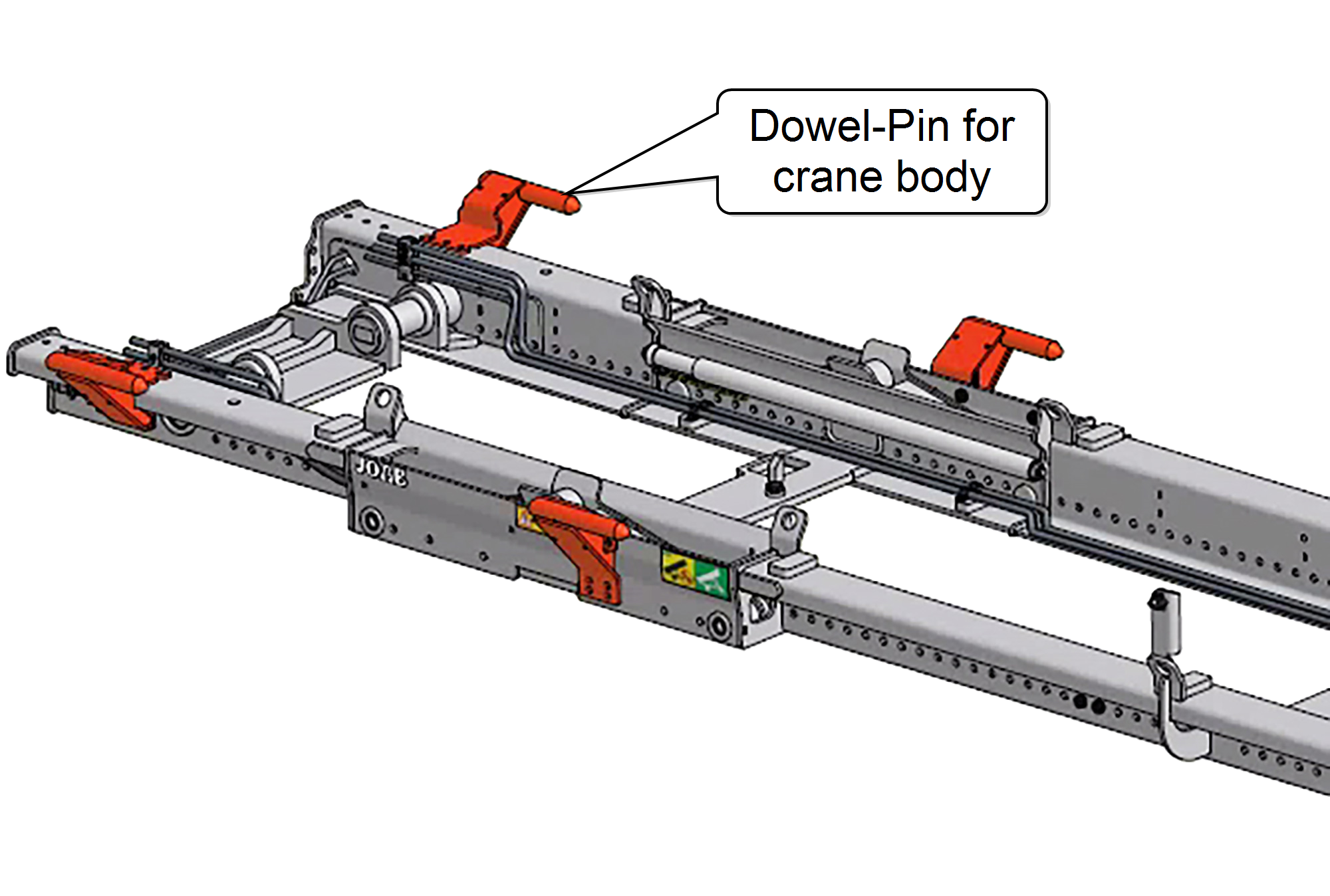 EcoDrivehooklifts that have been fitted with dowel-pins, as shown opposite, can be used to load a crane body.
All crane bodies used with EcoDrive must fulfill the following standard: SS 3021:2014.
The dowel-pins lock into corresponding dowel‑pin‑housings on the body and ensure that it is correctly secured onto the hooklift. The number of dowel-pins required is dependent upon the crane's lifting capacity.
Table 10 below lists the number dowel-pins required in relation to the lifting capacity of a crane.
| Crane Lifting Capacity (ton/meter) | Dowel-Pins Required |
|---|---|
| 16 | 2 |
| 22 | 4 |
| 28 | 6 |
Dowel-pins can be retro-fitted. For information regarding this please contact JOAB after sales department.
Activating a Crane
Read and adhere to all safety warnings and operating instructions in the crane's operator manual before operating a crane.
To operate a crane the CBW controller must first be turned on and the crane iconactivated from within the CBW controller.
When the crane icon is activated, the PTO is turned on and electricity is supplied to the crane. Once activated, a green pump iconwill be displayed in the top right-hand side of the CB controller and the crane active iconis displayed above the function buttons.
Operation of the crane is done using the crane's own control unit. This is a separate device and comes with its own operator manual. For information regarding the operation of the crane controller, please refer to its manual.
To prevent damage to the hooklift, it is not possible to tip the hooklift when a crane body is loaded. The hooklift is normally fitted with a sensor that detects if a crane body is loaded and prevents it from be tipped or shunted.