This chapter explains the operation of hooklifts that are electrically controlled only. For information regarding air controlled hooklift systems, refer to "Operation - Air Systems".
The hooklift can be controlled by a cab mounted controller or a radio controller. Radio controllers are an extra option. For further information see "Radio Controllers".
Electrical controlled systems manufactured after 2017 are equipped with a combined user interface and control stick, called the CBW controller. Systems earlier to this use a separate control stick and a LED display. For information regarding the CBW controller, refer to below. For information regarding earlier systems, refer to "Two Button Controller and LED Display".
CBW controller
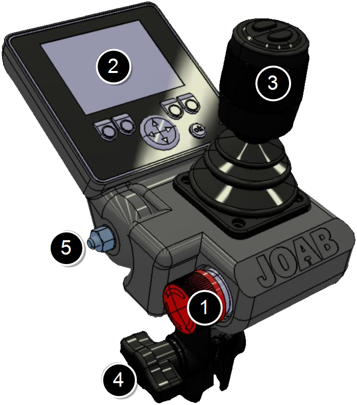 The CBW controller has both a display and control stick, as shown, and is used to control all functions of the hooklift.
Certain functions, such as the operation of the hydraulic pump, can be installed on the cab instrument panel, either in addition or separate from the CBW controller, as required.
The CBW controller has the fallowing main parts:
- Emergency Stop
- User Interface
- Control stick
- Mounting bracket
- Screen lock screw
The emergency stop button is used in case of an emergency. Once pressed, all functions of the hooklift that could cause injury are disabled. To restore operation the system must be restarted.
The user interface of the CBW controller has a 2.8 inch colour display. It is configurable. It is possible to display one of five different page set-ups. Each page set-up can have six user defined functions, such as turning lights on. For further information see "Page Set-Ups".
The control stick is used to control the basic functions of the hooklift, such as tipping. For detailed information regarding its function, refer to "Control Stick Function".
The mounting bracket is used to mount the unit inside the cab. Normally it is mounted onto the driver's A-post. However, it is also possible to mount it onto the driver's right arm rest. This is ideal for snow ploughs.
User Interface
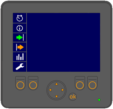
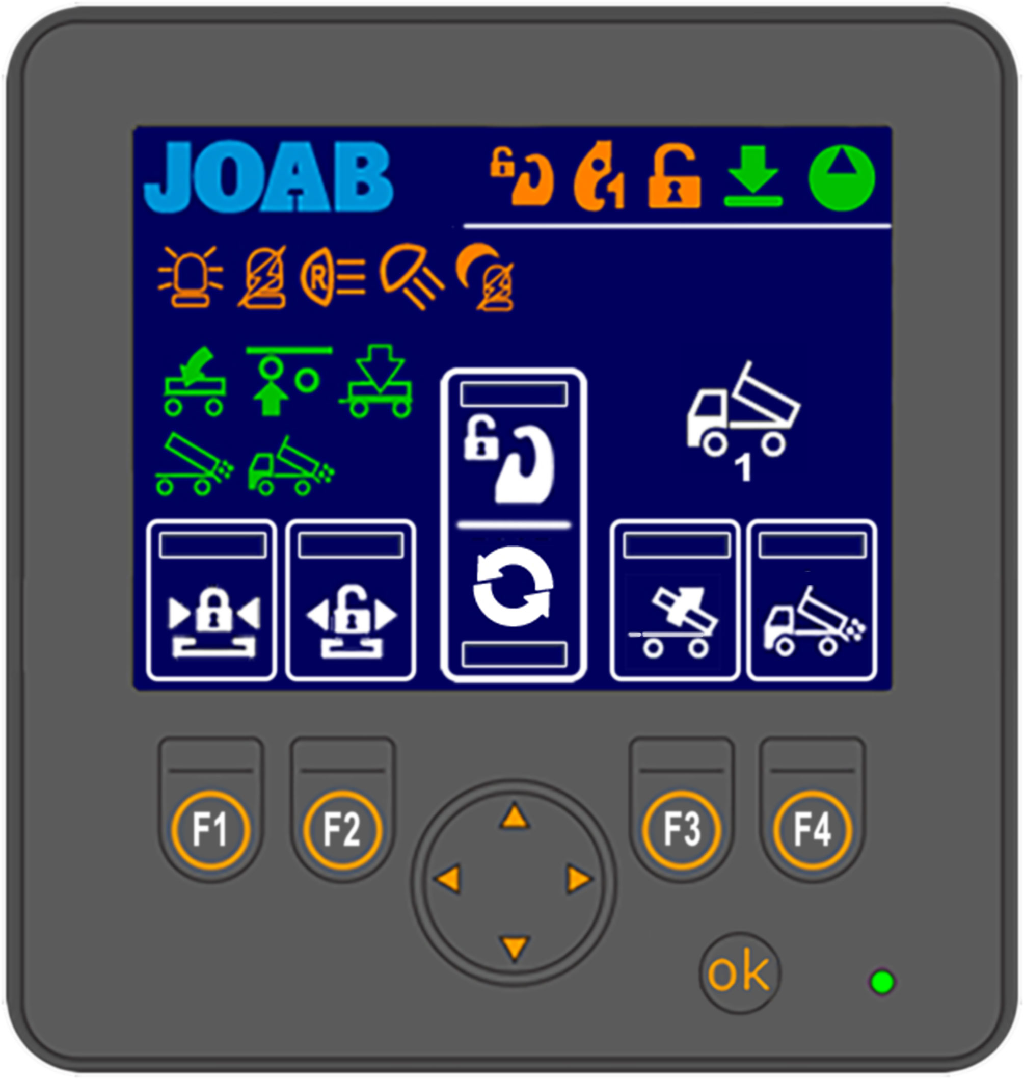 Shown opposite is an overview of the user interface.
The areas marked with a white rectangle on the screen are programmable. The user can set which functions are placed there. These functions are activated by pressing the corresponding buttons: F1–F4 and the UP/DOWN arrows. For further information on how to set these functions, refer to "Function Buttons" below.
The function icons (F1–F4 and the UP/DOWN arrow buttons) that are displayed in the user interface is dependent upon which page set-up is selected. There are five different page set-ups. To switch between these press either the left or right arrow button located below the screen. For more information see "Page Set-Ups".
All other icons that are displayed on the screen (not the user defined functions) simply provide feedback to the user regarding the status of the hooklift, which page set-up is active, and active functions, such as lights on etc.
See "Icon Definitions", below for a list of the icons and their function.
Icon Definitions
Provided below is a list of the functions available in the user interface and their meaning. Note, not all functions listed below are activated for all installations. Some of the functions are optional extras, these are marked with an asterisk (*).
Functions that can be selected for the programmable areas (F1–F4 and the UP and DOWN buttons) are coloured white. All other buttons (orange and green) simply provide feedback to the user as to whether or not they are active.
| Icon | Function | Icon | Function |
|---|---|---|---|

|
Night mode |

|
Automatic flap - VEHICLE* |

|
Load light -ON |

|
Tip trailer - UP* |

|
Back light - ON |

|
Tip trailer - DOWN* |

|
Flashing light - ON |

|
Draw bar* |

|
Red light - ON |

|
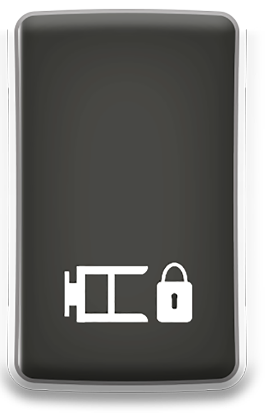
Hydraulic lock - CLOSE |

|
Center lock is OPEN |

|
Hydraulic lock - OPEN |

|
Safety hook is OPEN* |

|
Automatic flap - VEHICLE* |

|
Hydraulic lock is OPEN |

|
Continuous-hydraulic-supply (start/stop)* |

|
Hydraulic Pump (start/stop) |

|
Salt spreader* |

|
Air dump - TRAILER* |

|
Scraper* |

|
Axle lift - TRAILER* |

|
Snow plough* |

|
Automatic flap - TRAILER* |

|
Side plough UP on reverse* |

|
Spreader flap - VEHICLE* |

|
Start/stop the crane* |

|
The hooklift is in its lowered status. |

|
Axle lift - TRAILER* |
*Extra option. Not standard equipment. **LA models only.
Page Set-Ups
The user interface can display one of five main page set-ups, each configured with user defined functions. In addition, a page that displays information regarding the position of the hook on the hooklift can also be displayed. See "Hook Positioning" below. The pages available are listed below. The page set-up that is active is displayed in the bottom right-hand side of the screen with one of the following icons (see "User Interface").
| Icon | Description |
|---|---|

|
Vehicle setup_1 |

|
Vehicle setup_2 |

|
Trailer setup |

|
Lighting setup |

|
Snow plough setup |

|
Hook positioning display |
To switch between these page set-ups, simply press either the left or right arrow button below the display.
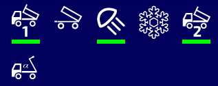
The number of menu page set-ups that are accessible via the left and right arrow buttons can be configured as required (1–5 page set-ups). In the example shown below, three page set-up are selected, these are shown with a green rectangle below them. The three active page set-ups will be visible when the left/right arrow buttons are pressed.
To configure which of the page set-ups are available when the left and right arrow buttons are pressed, follow the procedure below:
-
 Press and hold down the OK button and press either the left or right arrow button at the same time for a few seconds.
 - Select the desired page set-up from those displayed and then press the OK button to either activate it or de-activate it (active page set-ups have a green rectangle below them).
- Press and hold down the OK button for a few second to save the new settings.
The screen will then display the menu page options as shown.
Hook Positioning
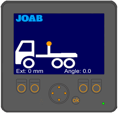 The hook position page option displays the position of the hook. As shown opposite, the position of the hook and its angle are displayed in the user interface whenever this menu page is selected (see also "Page Set-Ups"). This option is only available for L26 hooklift models and is dependent upon which optional sensors have been installed. For further information contact JOAB.
NOTE: This function is dependent on the hooklift's sensors. If the sensors malfunction or they are incorrectly positioned, the information displayed in the user interface will be incorrect. The actual information provided should be seen as an approximation and not an exact value.
Function Buttons
Each of the five page set-ups in the user interface can be configured with six personal functions. The icons for the selected functions are placed at the bottom of the user interface (shown in white rectangles, see "User Interface"). These functions are activated by pressing the corresponding function buttons below the screen: F1–F4 and the UP/DOWN arrow buttons.
To set the desired function associated with the function buttons, follow the procedure below:
- Press and hold the OK button while simultaneously pressing the function button that is to be changed.
- The current icon set for that function will be displayed with a green rectangle
around it, as shown below.
- Use the UP/DOWN arrow buttons to select the desired function.
- Press the OK button.
Background Light
The background light for the user interface can be adjusted as required. This function allows the user to quickly adjust the background light so that it is possible to read the display, when for example there is a lot of sun shining on the display.
To adjust the background light simply press the OK button with a short press repeatedly to switch between 100%, 20%, and 0% background light.
The display will automatically turn off whenever the hydraulic pump is off. It will only remain on if there is a warning to display, as listed under "Warnings". below.
Warnings
The user interface will display warnings whenever the hydraulic pump is not in operation. These warnings display an icon indicating the following states:
| Icon | Meaning |
|---|---|

|
The hooklift is not in drive status. It is not fully retracted. |

|
The center-lock is open. |

|
The hydraulic-lock is open. |

|
The safety-hook is open (LA models only). |
Control Stick Function
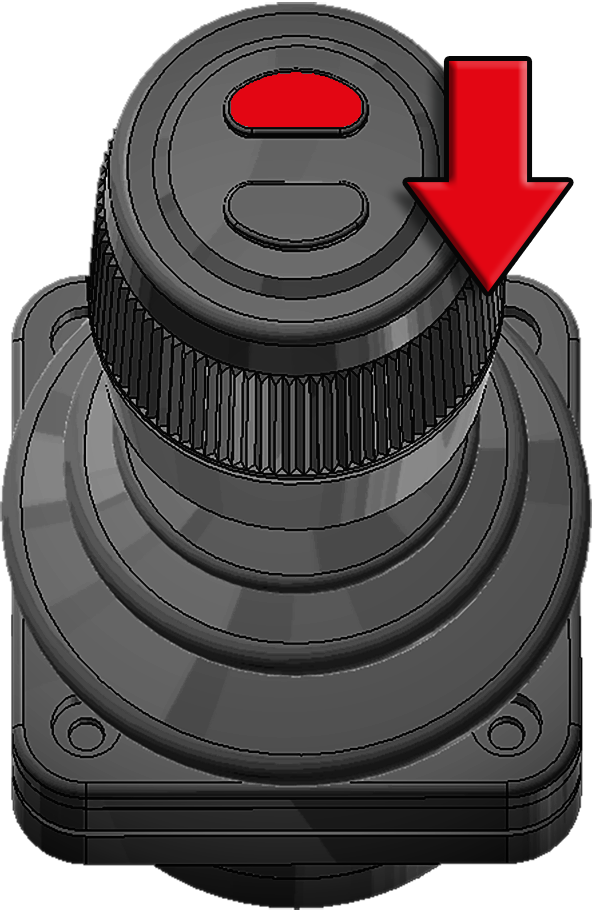
Listed below are the various functions that the control stick has. For information regarding the control of snow ploughs refer to "Snow Plough Functions".
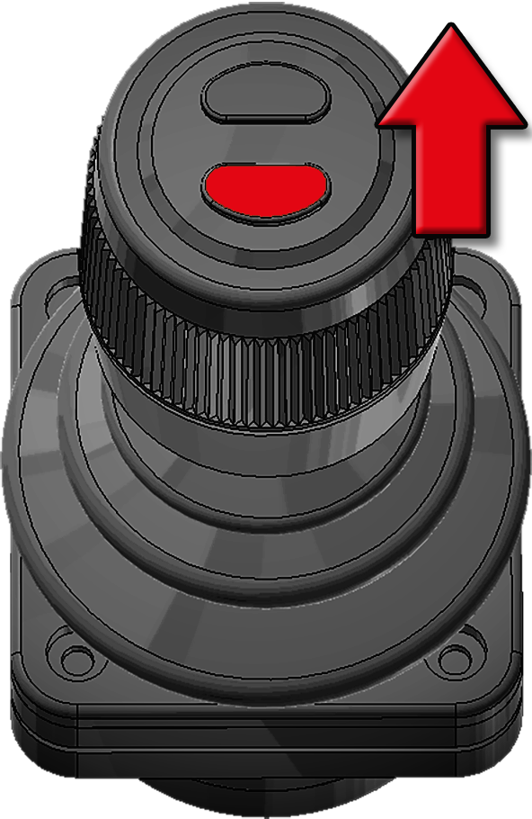
| Tip Up | Tip Up Fast Operation* |
Extending-Section IN |
|
|
|
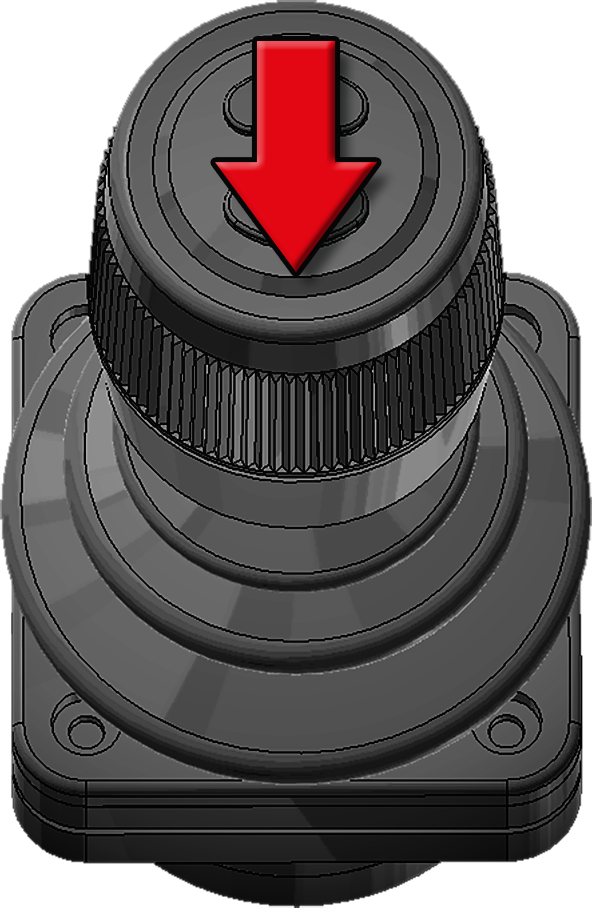
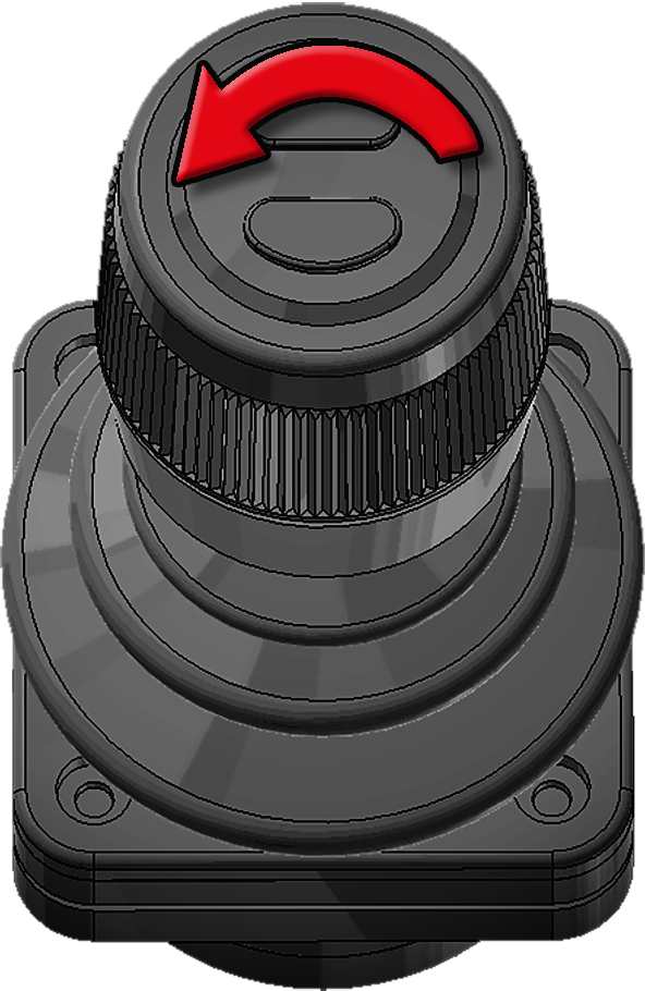
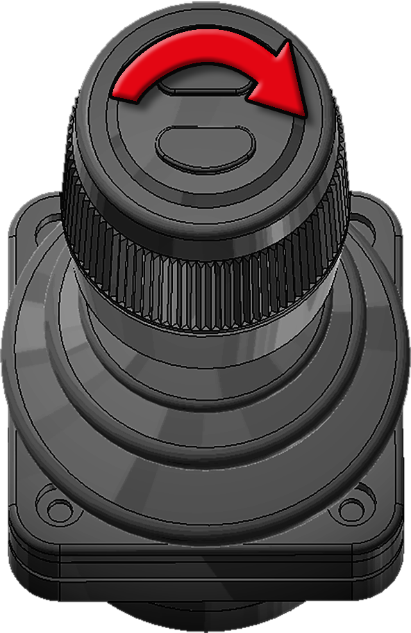
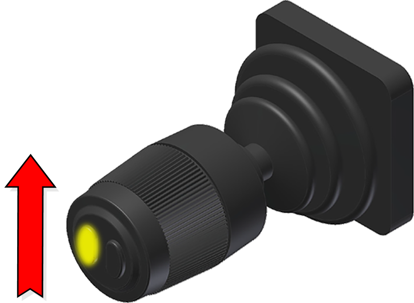
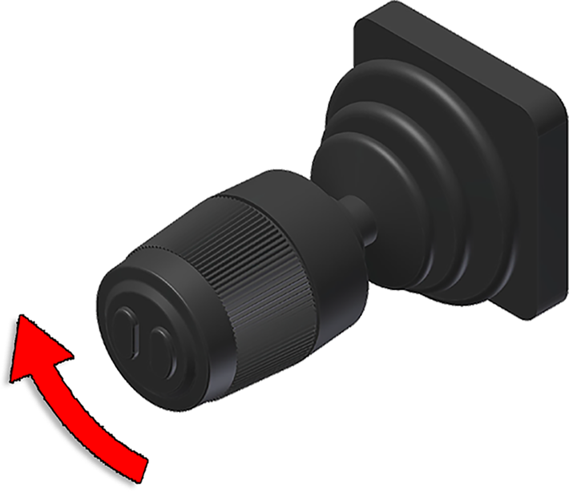
| Pull backwards | Bottom button pressed and pull backwards |
Turn the knob ant-clockwise |
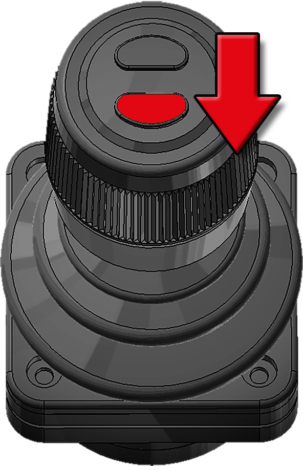
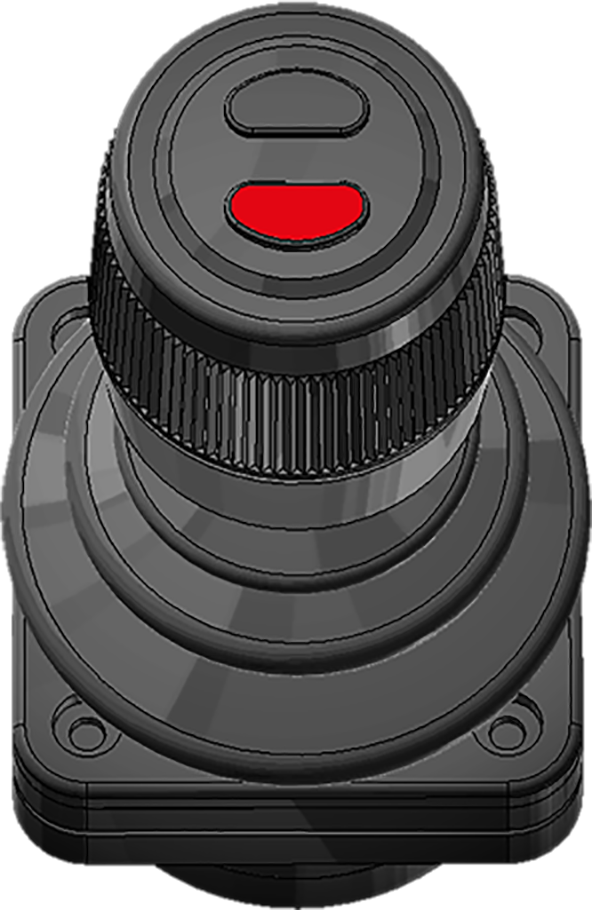
| Tip Down | Tip Down Fast Operation* |
Extending-Section OUT |

|
|
|
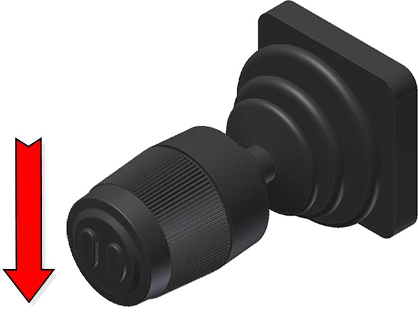
| Push forwards | Bottom button pressed and push forwards |
Turn the knob clockwise |
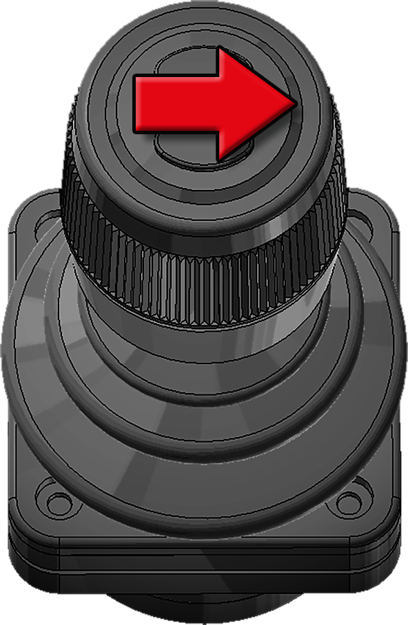
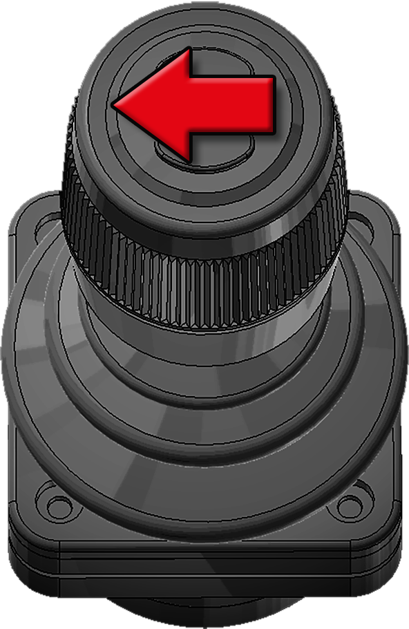
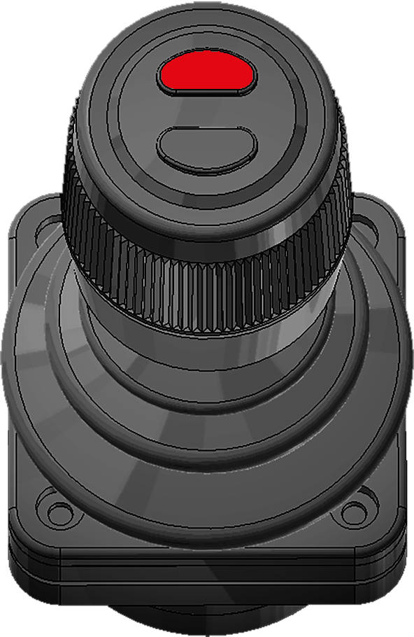
| Folding-Hook-Post UP** |
Folding-Hook-Post DOWN** |
Auto Cycle Load* |
|
|
|
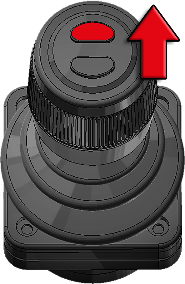
| Push the knob to the right | Push the knob to the left | Top button pressed and push forwards |
| Auto Cycle Unload* |
||
|
||
| Top button pressed and pull backwards |
*Extra option. For further information see "Extra Options". **LA models only.
Snow Plough Functions
Provided below are the functions for vehicles that have snow ploughs. Note, these functions are not standard. They are installed as additional options. To activate these functions the user interface must be in the snow plough page set-up . Refer to "Page Set-Ups".
The snow plough functions must first be activated in the snow plough page setup using the following icon .
.
Once the snow plough icon has been activated, it is then possible to operate the snow ploughs using the control stick. Simply push the control stick forward for a short period to activate the front snow plough. To initiate the side plough, simply press the top button, as shown below in Table 24.
Whenever a snow plough is active, a text message will be displayed in the snow plough page set-up stating which plough(s) are active.
Diagnostics and Statistics
The CBW controller has a diagnostic and statistics page that the user can view. The information provided in this page includes:
- Time that the system has been active.
- Time the power has been active.
- The number of shunts done.
- The number of tips done.
- The software version (not all units).
- Which sensor is active.
- Control stick diagnostic information.
- Certain installations packets.
- Diagnostic information for outputs.
 To access the menu, first make sure that one of the main menu pages is displayed and then press and hold down the OK button for a few seconds. The screen shown opposite will then be displayed.
Use the arrow buttons to navigate the menu. The up and down arrow buttons navigate through the menu. The left and right arrow buttons allow the user to select from options when applicable.
To exit the diagnostic and statistical menu, press and hold down the OK button for a few seconds.
Limp Home Mode
The CBW controller has a limp-home function. In the event that either the display or the control stick fails, it is still possible to operate the hooklift, as described below.
To initiate the limp-home function, turn the vehicle's ignition off and then back on. Then press and hold down buttons F1 and F4 (see "User Interface"), simultaneously, while the unit loads. Once in limp-home mode, the hooklift can be operated by pressing the following buttons.
| Button | Function |
|---|---|
| F1 | Hydraulic lock – LOCK |
| F2 | Hydraulic lock – OPEN |
| Arrow-UP | Tip UP |
| Arrow-DOWN | Tip DOWN |
| Arrow-LEFT | Extending section – EXTEND |
| Arrow-RIGHT | Extending section – RETRACT |
Continuous-Hydraulic-Supply
The CBW controller can be used to set and adjust a constant hydraulic feed to a tip-trailer. This is not standard, it must be ordered as an extra option.
The continuous-hydraulic-supply is not the same as tipping or lowering a trailer. When the trailer is simply lowered or tipped, a hydraulic feed is provided only during the time the function is activated. In contrast, the continuous-hydraulic-supply is constantly fed to the tip-trailer and can be either increased or decreased as required. Note, not all vehicles are equipped with the ability to increase or decrease the flow of hydraulic fluid.
The hydraulic supply to a tip trailer is normally fed from the hooklift's connector on the back of the vehicle.
The CBW controller is used to control the flow of hydraulic fluid to the tip-trailer. The flow is initially set at 0L/min and must be set to the required value by the driver using the tip trailer icons. Refer to Table 26.
Once a value for the hydraulic supply has been set, using the tip-trailer icons, it is saved. If the unit or power supply is turned off, the value is still saved. It can be changed again, if desired, at any time.
After setting the continuous-hydraulic-supply, it can be started by simply selecting its icon, as shown below. The hydraulic supply will flow at the saved rate of flow.
There is no hydraulic flow sensor in the supply line to the tip trailer. Therefore, an external flow sensor will be required if the hydraulic flow is to be measured.
To operate the hydraulic supply to the tip trailer use the functions listed below.


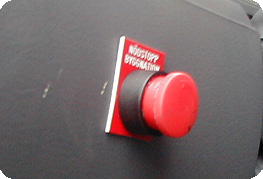
Emergency Stop
In case of an emergency, such as a hydraulic leak or risk of injury, an emergency stop button is fitted to the CBW controller (see "CBW controller"). Pressing the emergency stop button will stop all functions of the hooklift immediately. To reset the emergency stop function, first make sure the stop button is reset. Then restart the hydraulic pump.
Two Button Controller and LED Display
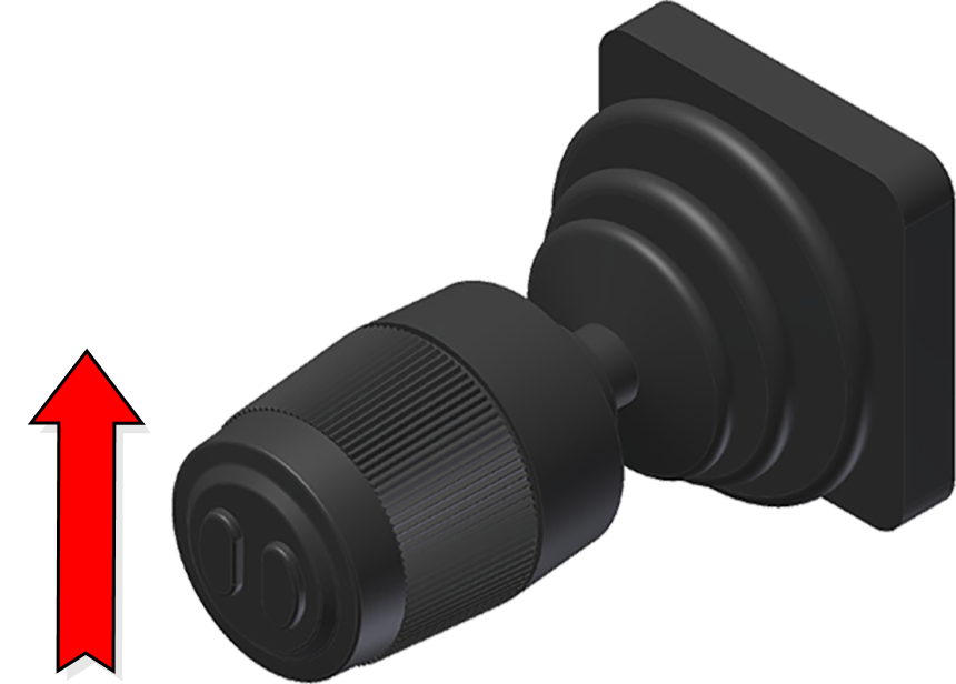
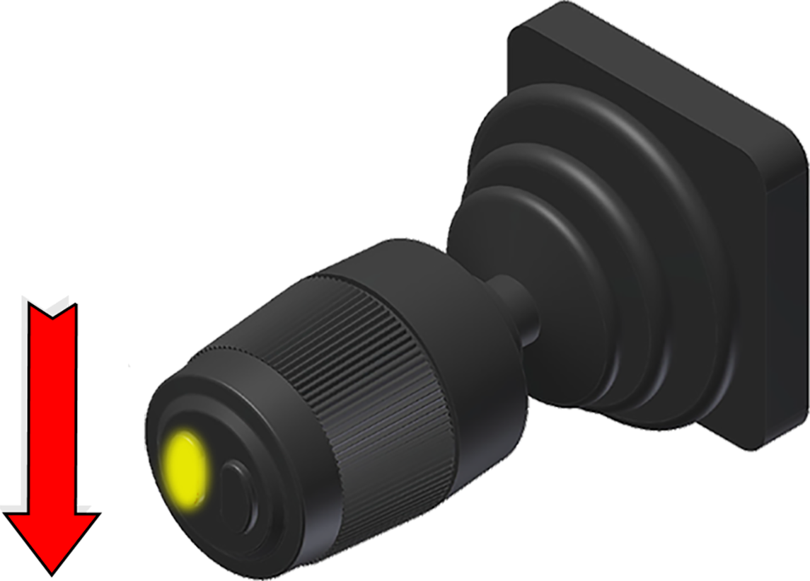
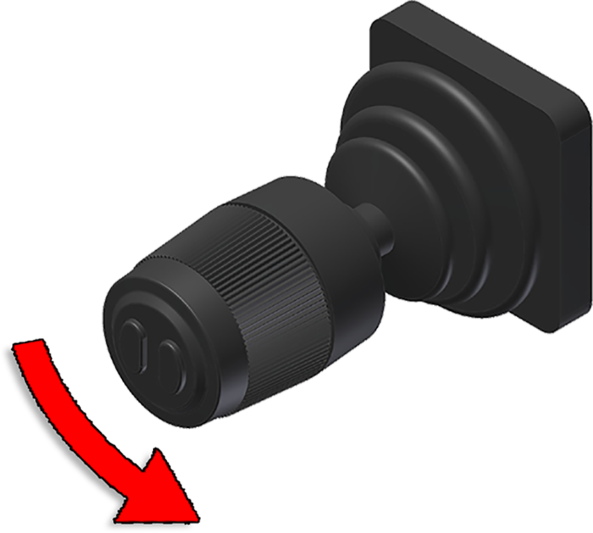
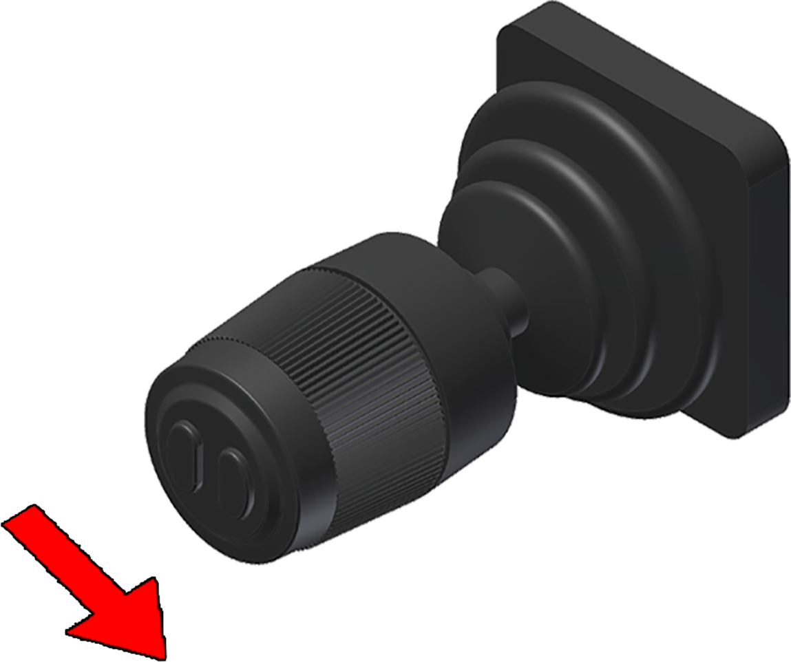
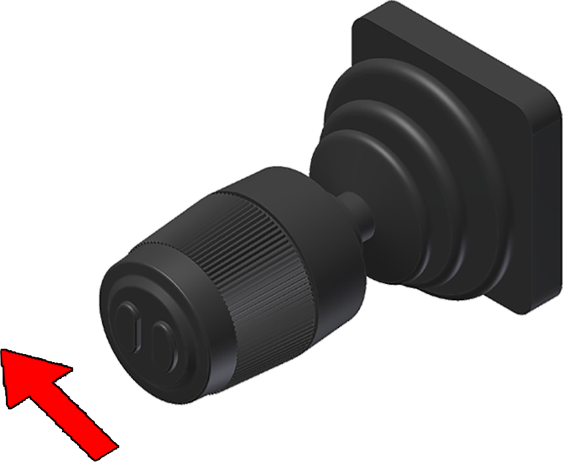
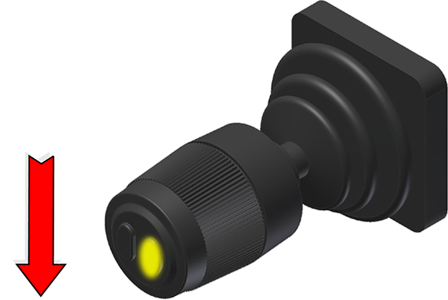
hooklift installations prior to the CBW controller have a controller installed as shown below in Table 27. It is normally mounted on the left-hand side of the driver’s seat. There are two buttons on the front of the controller's knob.
The controller is used for both L and LA hooklifts. For further information regarding its function refer to below.
Cab-Controller Operation
Provided below is information on the use of the cab-controller and the functions that the buttons have.

*Extra option. For further information see "Extra Options". **LA models only.
LED Display and Buttons
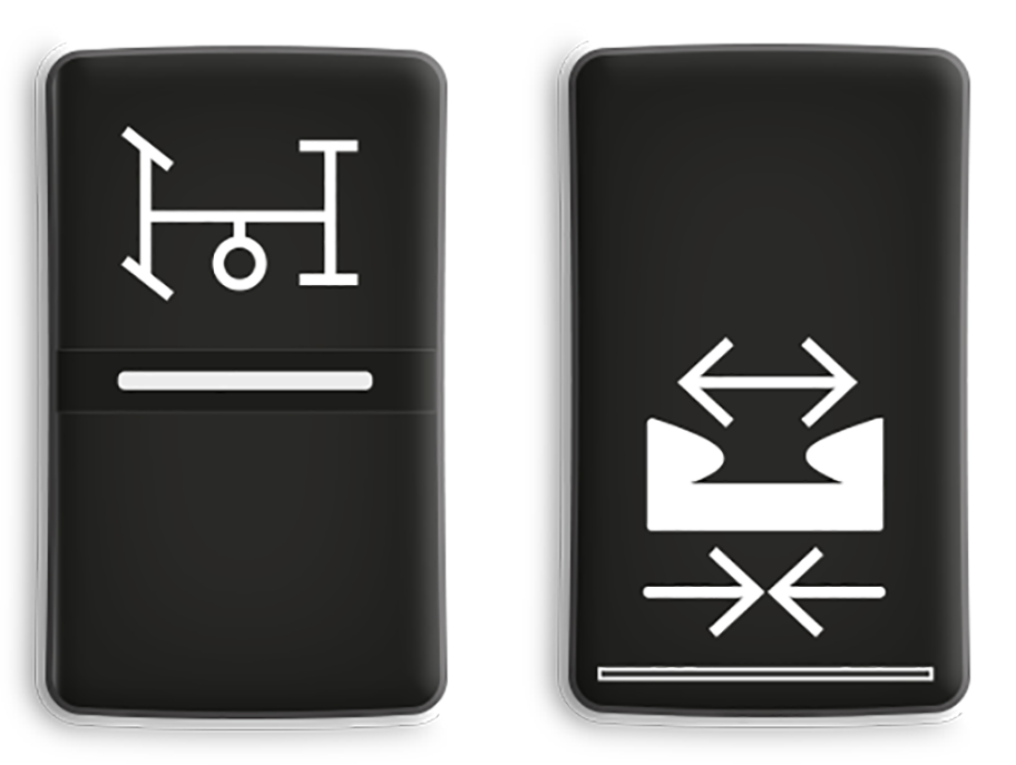 Operation of the hydraulic-pump and the hydraulic-lock is controlled using the installed buttons as shown opposite (left and right button, respectively). These are JOAB's standard buttons. However, it is possible that the vehicle's own buttons are used instead of those shown. The driver should familiarize themselves with which buttons are actual for the operation of the hooklift.
The buttons are normally installed on the driver's dashboard. Depending on options ordered, there may also be more buttons installed for the additional options.
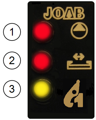 The status of the hooklift is displayed inside the vehicle using JOAB's own LED display. The display is normally mounted on the drivers dashboard and has three warning LEDs, as follows:
- The hydraulic pump is active - RED.
- The hydraulic-lock is OPEN - RED.
- The center-lock is OPEN - YELLOW.
Some vehicles are equipped with a hydraulic pump lamp that will also illuminate whenever the hydraulic pump is active. This is not JOAB equipment. Read the vehicle’s manual and make sure that you are aware of the relevant equipment for the vehicle being operated.
Trailer Warming Lights
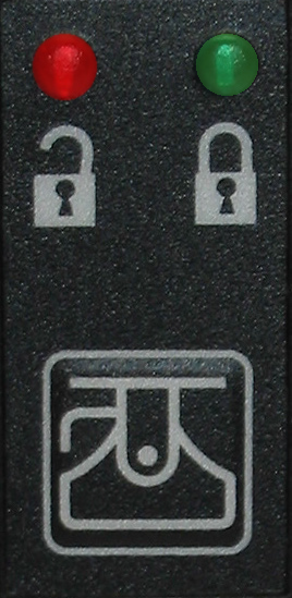 For vehicles with auxiliary equipment such as a tow hitch for trailers, an additional display will also be fitted, as shown. The red LED indicates that the tow-hitch is OPEN. The green LED indicates that it is closed.
 Certain manufacturers, such as Scania, have a reset switch for the tow-hitch's servo. This must be pressed to deactivate the warning for the tow-hitch after it has been locked. If it is not reset, the warning for the tow-hitch will remain active both on the LED panel, and in the driver's display, where applicable.
Emergency Stop
In case of an emergency, such as a hydraulic leak or risk of injury, an emergency stop button is fitted to all vehicles.
 Pressing the emergency stop button will stop all functions of the hooklift immediately. The button is usually placed below the steering wheel, in the cab.
To reset the emergency stop function, pull the button out, reset all functions to neutral, then switch off and restart the vehicle's engine.
Extra Options
A number of options can be purchased for operating additional functions with the hooklift as well as a trailer. These are discussed below:
- Fast operation
- Auto-cycle
- Snow plough functions
- Trailer functions
Fast Operation
This function can be used when tipping a load UP or DOWN. Fast operation of the tip-DOWN function will only work when there is a load on the hooklift. The weight of the load is used to force the hydraulic fluid from the hydraulic cylinders, which causes fast operation to work. The heavier the load, the faster the operation will work.
Fast operation of the hooklift can also be used when in shunting mode (the centre-lock is open) and only when moving the hooklift backwards without a load.
Do not use fast operation of the hooklift in shunting mode when there is a load on the hooklift. Damage to the equipment can occur if fast operation is used in shunting mode with a load. When fast operation is used, the return line of the hydraulic cylinder is fed back into the supply line of the hydraulic cylinder.
Auto-Cycle
As an extra option, the cab controller can also be equipped with an automatic cycle function. This is used to load or unload a body in one continuous cycle. The auto-cycle function has the following procedures:
- Open the hydraulic lock - manually
- Extending-section is retracted 250 mm
- Auxiliary arms are activated
- Extending-section is fully retracted
- The body is unloaded
- The safety-hook is opened (LA models only)
Auto-Cycle – Unload
- The safety-hook is locked
- The body is loaded onto the hooklift
- Auxiliary arms are activated
- Extending-section is partly extended
- The body is fully lowered
- The extending-section is fully extended
- The hydraulic-lock is locked
Auto-Cycle – Load
Trailer Functions
Functions specific for trailers can also be purchased as an option. These include functions such as tipping, spreader flap control, and automatic flap. For further information regarding all options available contact JOAB.
Snow Plough Functions
The cab controller can be equipped with functions for controlling snow ploughs. These functions allow the driver to control both a front and side snow plough. These options are only applicable for the CBW controller. For information regarding the operation of snow ploughs, refer to "Snow Plough Functions".