A radio operated controller can be bought as an option for all hooklifts. These allow for operation of the hooklift remotely. The operator does not need to be in the vehicle to operate the hooklift.
The use of a radio controller allows the operator to have a good visual overview of the lifting operation. This can be beneficial in many aspects.
When the radio controller is active, the cab-controller, mounted inside the cab, can not be operated.
There are two types of radio controllers. One for electrical controlled hooklift systems, see "Operation – Electrical Systems". And one for air controlled hooklift systems, see "Operation – Air Systems".
Before Operation
Personnel must be trained in the use of radio controllers before being allowed to use them. Serious injury or damage to the environment can result if a radio controller is operated incorrectly.
The operator must make sure that they are fully aware of the surrounding environment and equipment.
The operator must be fully focused on the operation of the controller and lifting equipment. Do not operate the radio-controller when performing other tasks.
Make sure that a safe working distance of at least four meters exists around the lifting equipment. Failure to do so can lead to serious injury.
Do not leave a radio controller unattended. When the controller is not in use, make sure it is turned off.
 Operation – Electrical Systems
Provided below is an overview of the radio controller for electrical controlled hooklift systems only. For information regarding radio controllers for air controlled systems, see "Operation – Air Systems".
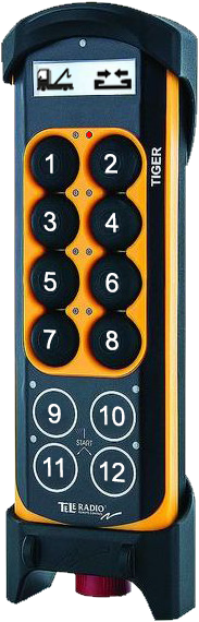
Operation of the hooklift is made using the main control buttons 1-12, as shown opposite.
Information regarding operation is displayed in the controller's display, located at the top of the controller.
Buttons 1–8 are analogue. Pressing these buttons harder will cause the operation that it controls to happen faster. Alternatively, these buttons can be set to simply have an ON/OFF function.
Buttons 9–12 are digital and used for simple functions, such as the operation of a spreader flap.
The buttons 1–12 are multifunctional. That is, they can have more than one function assigned to them. See "Function Mode" below.
Display
The display at the top of the controller displays information regarding the current function mode selected and the function currently activated. In the example shown, the truck symbol indicates that function mode_1 is selected and that the current function being operated is the hydraulic-lock.
LEDs
Each button has an LED located to the left or right of it. In the example shown, the LED to the left of button 2 is illuminated green. These LEDs are used to provide information regarding current status of the active operation. Listed below is table describing what each relevant LED means.
Emergency Stop
The large red emergency STOP button located at the bottom of the controller is used to stop the hooklift in an emergency. To activate it, simply push it in. It must be pulled out to start the controller.
Function Mode
Buttons 1–12 are multifunctional. They can have three functions assigned to them. These are related to the function mode selected for the controller (Function_1, Function_2, or Function_3).
To select the desired function mode, simply press button 12 after start-up of the controller. By default, function mode_1 is operative at start-up. The LEDs next to buttons 11 and 12 indicate which function mode is operative, see Table 74. If function mode 1 is active the LEDs for buttons 11 and 12 are not illuminated.
Listed below is an overview of the buttons and their functions in relation to which function mode has been selected.
* Option: Not standard equipment.
Start the Radio Controller
Follow the instructions below to start the remote control unit.
- Ensure that the stop button is pulled out.
- Hold buttons 11 and 12 pressed in together until an audible signal is heard.
- Check that the display is activated.
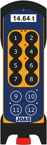 Axle Weight Reading
The radio controller can be used to provide an approximate value for the weight on an axle(s). Note, this is not a precise value and must be seen as an indication of the actual weight only.
JOAB AB disclaims all responsibility if a vehicle is over weight, even if the radio controller displays a value that is lower then the maximum allowed for the vehicle.
The value displayed in the radio controller will normally be within ± 150 kg.
To activate the axle weight mode, press button 12 repeatedly, until a weight scale is shown. To select which axles are included in the measurement, press the respective buttons: 2, 4, 6, and 8 corresponding to the axle(s) that are to be measured.
Each of the buttons (2, 4, 6, and 8) have two LEDs above them. These are used to show which axles are selected and the status of the axles. The right LED is illuminated red for axles that are selected, as shown. The left LED will blink red whenever an axle is 0–500 kg less than the maximum allowed weight. The left LED will constantly illuminate if an axle is over its allowed weight.
The LED above button 9 is used to indicate that it is the net weight that is displayed in the screen. When the net weight is displayed, the LED is lit red. To change between the net weight and the gross weight press button 9.
Charging
 The charger for the radio controller is normally mounted next to the driver's A-post inside the cab. Alternatively, it is mounted in the driver's side toolbox, behind the door.
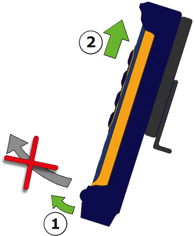
When not in use, always place the radio controller in its charger. This will ensure that it is always fully loaded and ready for operation.
To remove the radio controller from the charger, first pull the bottom out a small amount, approximately 10 mm, and then push the controller up, as shown.
Do not pull the controller out from the bottom. This will cause damage.
 Operation – Air Systems
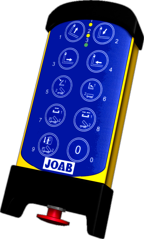
Provided below is an overview of the radio controller for air controlled hooklift systems.
Operation of the hooklift is made using the main control buttons 0-9, as shown opposite.
LEDs
There are three LEDs at the top of the controller. Two yellow (1 and 2) and one green (3). LEDs 1 and 2 indicate which function mode is selected, refer to "Function Mode" below.
LED 3 is lit green when the controller is active and red when the battery is low.
Emergency Stop
The large red emergency STOP button located at the bottom of the controller is used to stop the hooklift in an emergency. To activate it, simply push it in. It must be pulled out to start the controller.
Function Mode
LEDs 1 and 2 (yellow) indicate which mode the controller is in. Either Function_1 or Function_2.
Buttons 5–9 have the numbers 1 and 2 written on them and have two functions. These are related to the function mode selected for the controller (Function_1 or Function_2).
To select the desired function mode, simply press button 0 after start-up of the controller, until LED 1 or LED 2 is illuminated.
Listed below are the radio controller's buttons and their functions in relation to which function mode has been selected.
| Button | Function mode 1 | Function mode 2 |
|---|---|---|
| 1 | Tip UP | Tip UP |
| 2 | Tip DOWN | Tip DOWN |
| 3 | Sledge backwards | Sledge backwards |
| 4 | Sledge forwards | Sledge forwards |
| 5 | Hook-post – UP | Trailer tip – UP |
| 6 | Hook-post – DOWN | Trailer tip – DOWN |
| 7 | Hydraulic lock – OPEN | Spreader flap truck – UP* |
| 8 | Hydraulic lock – LOCK | Spreader flap truck – DOWN* |
| 9 | Safety hook | Automatic flap, truck |
| 0 | Select function mode | Select function mode |
* Option: Not standard equipment.
Start the Radio Controller
To start the radio controller, follow the procedure listed below:
- Make sure that the STOP button is pulled out.
- Press buttons 9 and 0 in for at least one second and then release them.
- Verify that LED 3 is lit green. When lit the controller is active.